
PIC16F84A based LC Meter circuit with explanation
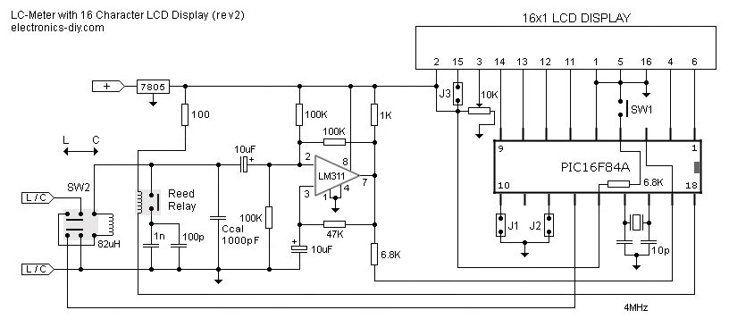
The LC inductance/capacitance meter circuit is designed to provide precise measurements of inductance and capacitance values across a broad range. The core of the circuit typically includes an oscillator, a microcontroller, and a display unit. The oscillator generates a signal whose frequency is influenced by the component being measured. This frequency is then processed by the microcontroller, which calculates the inductance or capacitance based on the frequency shift caused by the connected component.
The auto-ranging feature is achieved through a combination of analog and digital techniques. The circuit continuously monitors the frequency and adjusts the measurement range accordingly, allowing for seamless transitions between different measurement scales. This is particularly beneficial when measuring components with unknown values, as it saves time and enhances user experience.
The Zero Out function is an important aspect of this meter. By allowing the user to reset the baseline measurement, it compensates for any parasitic capacitance or inductance that may affect the accuracy of the readings. This is crucial for obtaining reliable data, especially in precision applications.
In terms of construction, the circuit can be built using readily available components such as resistors, capacitors, inductors, and a microcontroller (like an Arduino or similar). The design can be implemented on a PCB or a breadboard, depending on the user's preference. The display unit can be an LCD or LED, providing clear visual feedback of the measurements.
Overall, this LC meter represents an effective solution for hobbyists and professionals alike, enabling accurate measurements of inductance and capacitance in a user-friendly format.This is one of the most accurate and simplest LC inductance / capacitance Meters that one can find, yet one that you can easily build yourself. This LC Meter allows to measure incredibly small inductances starting from 10nH to 1000nH, 1uH to 1000uH, 1mH to 100mH and capacitance from 0.
1pF up to 900nF. LC Meter`s circuit uses an auto ranging system so that way you do not need to spend time selecting ranges manually. Another neat function is the Zero Out switch that will reset the initial inductance / capacitance, making sure that the final readings of the LC Meter are as accurate as possible. Disclaimer All files are found using legitimate search engine techniques. This site does not and will not condone hacking into sites to create the links it list. We will and do assume that all links found on the search engines we use are obtained in a legal manner and the webmasters are aware of the links listed on the search engines.
If you find a URL that belongs to you, and you did not realize that it was "open to the public", please use the report button to notify the blogmaster of your request to remove it or it will remove within 24 hours. This is not an invitation for webblog haters to spam with requests to remove content they feel that is objectionable and or unacceptable.
Proof of URL ownership is required. NOTICE: This Blog Has Already Been Reviewed And Accepted By Blogger. com 🔗 External reference
Related Circuits
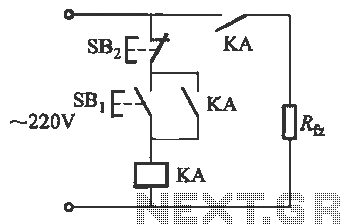
Power outages following a call prevent the re-closure of a circuit, which can help avoid the use of electrical appliances after the power grid is restored. If appliances are left on and a call occurs, it may lead to...
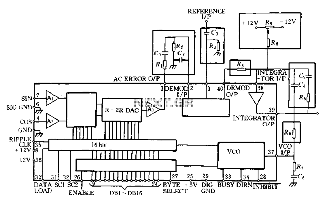
The AD2S80A RDC tracking monolithic integrated circuit is Analog Devices' latest generation RDC. It can be utilized for synchro, resolver, and inductive synchronizer digital conversion. This device integrates advanced CMOS logic and bipolar high-accuracy linear circuits using a BiMOS...
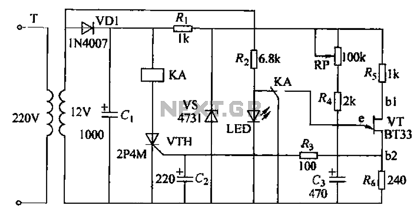
The circuit consists of a delay loop, discriminators, output circuits, power supply, and indicator lights, divided into five parts. The power regulation is achieved through a resistor (R), while the power regulator is constructed using a voltage source. In...
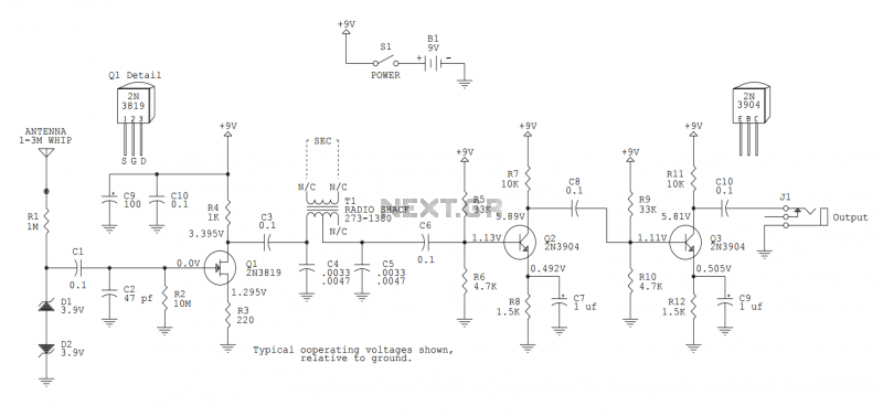
This version sports a 2nd audio amplifier stage at Q3. The output level with this version is sufficient to drive a crystal headphone to a comfortable volume. The "crystal" headphone is like those used on ye olde crystal radios....
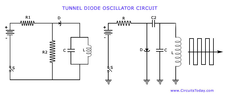
The operation of Negative Resistance Oscillators, including types such as Dynatron and Tunnel Diode Oscillator, along with their characteristics and circuit diagrams, is explained. Negative resistance oscillators are electronic circuits that exploit the phenomenon of negative resistance to generate oscillations....
The circuit described below is notable for its low power consumption. With a 9V input and no load at the output, it draws only 50 mA, which is significantly lower than the quiescent current of a 78L05 regulator. The...