
JS20 single-junction transistor time relay circuit
The circuit design employs a half-wave rectifier configuration, which is efficient for converting AC to DC power. The diode (VD1) plays a critical role in allowing current to pass in one direction, thus charging the filter capacitor (C1) and providing a stable DC voltage to the subsequent components. The use of a single-junction transistor (VT) as a switch is advantageous due to its low drive requirements and fast response time, which is essential for applications requiring quick on-off control.
The charging behavior of capacitor (C4) is exponential, governed by the RC time constant defined by the resistor (RP1) and the capacitor's capacitance. This time constant dictates the delay before the transistor (VT) activates. The relay (KA) is used to control larger loads, providing isolation between the control circuit and the output circuit. The LED indicator serves as a visual cue, confirming the operational status of the circuit.
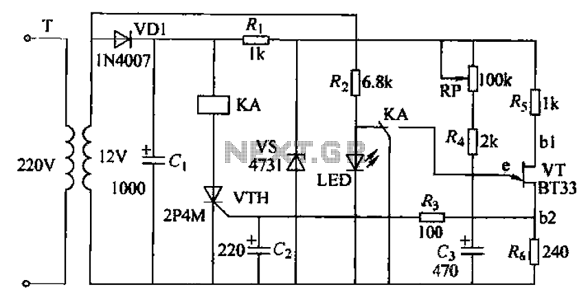
The rapid discharge of capacitor (C3) through the relay contacts ensures quick response times, which is crucial for applications where timing is critical. The design allows for fine-tuning of the delay interval, making it versatile for various applications requiring precise timing control. Overall, this circuit exemplifies a reliable solution for delay-based operations in electronic systems. Circuit by the delay loop, discriminators, output circuits, power and lights of five parts. Part of the power regulator by resistance R, and the regulator vs constituted power as part of the delay, the output circuit of the thyristor VTH and relay KA by a half-wave rectifier circuit powered directly. The circuit works as follows: When the power is turned on, the diode VD1 rectifier, filter capacitor cl and after RJ and VS regulator, by RP1, R4 G capacitor is charged.
Capacitor voltage G gradually increased exponentially, when this power when pressure is greater than the single-junction transistor VT peak voltage, single- junction transistor is turned on, G pole and wind through the VT eb1 discharge in wind output pulse voltage trigger Phan brake pipe VTH conduction pull the relay KA, KAs contacts while the short circuit C3, so that the rapid discharge, single -junction transistor voltage between ebl rapid decline, when descending to Vr. Valley point voltage, Vr is closed. At the same time LED indicator lights. When the power is turned off, the relay KA release circuit to restore the original state, waiting for the next action.
By adjusting the RP. You can adjust the delay time.
Related Circuits
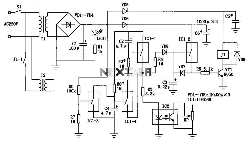
A cable radio broadcasting studio in rural villages and towns is often equipped with high-power amplifiers that are susceptible to damage. This vulnerability primarily arises from frequent usage without specialized management, leading to situations where the system is often...
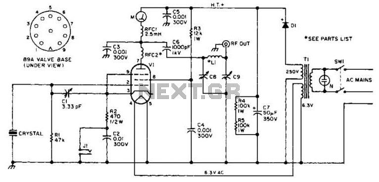
This transmitter operates on a 9-V battery and can function as a wireless microphone compatible with standard 88- to 108-MHz FM broadcast receivers. To adhere to FCC regulations, the antenna length should not exceed 12 inches. The inductor L1...
The goal is to utilize a PC to measure the outdoor temperature using a serial-connected device equipped with a probe that can be conveniently placed outside. Although various options were found through online searches, many appear to be overly...
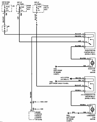
The 1996 Suzuki Esteem Cooling Fan system includes a control relay for the radiator fan (located in the relay box), air conditioning fan motor, radiator fan motor, condenser fan motor, junction box, fuse and relay box, and engine control...
The working principle of this inexpensive and simple-to-build metal detector circuit involves mixing two equal frequencies, which results in a low-frequency interference. The metal detector circuit operates on the principle of heterodyning, where two frequencies are combined to produce a...
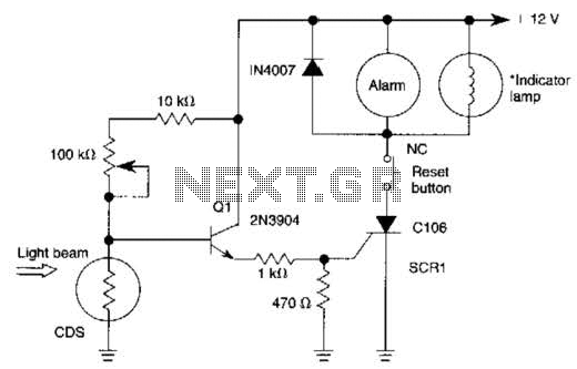
When the light beam that falls on the CDS photocell is interrupted, the transistor (EN3904) conducts, triggering SCR1 (CI06) and activating the alarm bell. SI resets the SCR. The alarm bell should be a self-interrupting electromechanical type. The lamp...
Warning: include(partials/cookie-banner.php): Failed to open stream: Permission denied in /var/www/html/nextgr/view-circuit.php on line 713
Warning: include(): Failed opening 'partials/cookie-banner.php' for inclusion (include_path='.:/usr/share/php') in /var/www/html/nextgr/view-circuit.php on line 713