
pic16f877 based controllable digital clock using lcd display codeproteus simulation
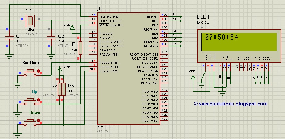
The implementation of a controllable digital clock using the PIC16F877 microcontroller involves several key components and steps. The PIC16F877 is an 8-bit microcontroller with a variety of features that make it suitable for timing applications, such as built-in timers, I/O ports, and EEPROM for data storage.
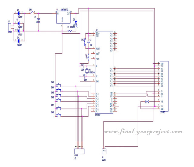
The circuit design begins with the microcontroller connected to a crystal oscillator to provide the necessary clock signal for accurate timing. A common frequency for the oscillator is 4 MHz, which allows the microcontroller to execute instructions efficiently. The oscillator circuit typically includes two capacitors connected to the crystal to stabilize the frequency.
The digital clock will require an interface for user input, which can be achieved using push buttons or a keypad. These inputs will allow users to set the time and switch between display modes (e.g., 12-hour or 24-hour format). The microcontroller's GPIO pins can be configured to read the state of these buttons.
For timekeeping, the microcontroller can utilize its internal timer modules. A timer interrupt can be configured to trigger every second, allowing the program to increment the time count accurately. The time can be stored in the microcontroller's RAM or EEPROM, depending on whether persistent storage is required.
The display of the clock can be implemented using a 7-segment LED display or an LCD module. The microcontroller will control the segments or characters displayed based on the current time value stored in memory. It is also essential to include a driver circuit for the display, especially if using multiple 7-segment displays, to handle the current requirements.
Power supply considerations are crucial for the clock circuit. A stable power source, such as a regulated 5V supply, should be used to ensure consistent operation. Additionally, the design may include a battery backup system to maintain time during power outages.
Lastly, the programming of the PIC16F877 can be accomplished using MPLAB IDE and XC8 compiler. The code will handle input reading, time calculation, display updates, and any additional features such as alarms or timers, providing a comprehensive solution for a controllable digital clock.This PIC16F877 microcontroller tutorial answers the question, "" How to implement a controllable digital clock using PIC16F877 ? "" Using PIC16 simulator (Pr.. 🔗 External reference
Related Circuits
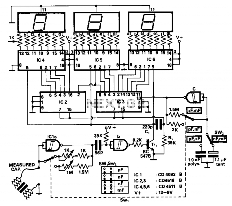
The operation principle involves counting the number of pulses generated by a constant frequency oscillator over a fixed time interval, which is produced by another lower frequency oscillator. This lower frequency oscillator utilizes the capacitor being measured as the...
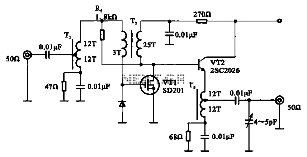
A broadband amplifier circuit utilizing a negative feedback amplifier configuration is presented. This circuit employs transformer coupling and a combination of amplifying sections and field-effect transistors (FETs). The input signal is applied to the center tap of the transformer...
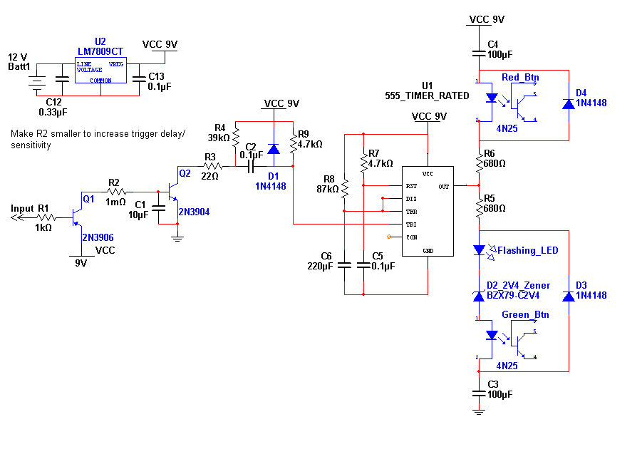
This entry is for the international 555 Contest. The 555 timer chip has been in use for many years and is highly versatile. The concept of this project addresses the need for notification of an event while away from...
This project is a microcontroller-based college automation system aimed at addressing the challenges faced in educational institutions. It replaces the conventional notice board with an automated device that allows users to both hear and read the information being announced...
This circuit functions as an ultra-low power alternative to multiple LED on-off indicators. It is designed to be easily readable in full daylight conditions. The described circuit employs a low-power microcontroller or a dedicated LED driver IC that manages the operation...
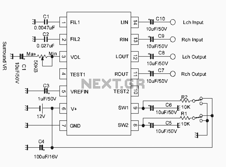
The NJM2701 3D surround sound audio processor integrated circuit can be designed into a very simple 3D surround sound system. The NJM2701 reproduces 3D surround sound using only two speakers and is suitable for various audio applications, including micro-components,...
Warning: include(partials/cookie-banner.php): Failed to open stream: Permission denied in /var/www/html/nextgr/view-circuit.php on line 713
Warning: include(): Failed opening 'partials/cookie-banner.php' for inclusion (include_path='.:/usr/share/php') in /var/www/html/nextgr/view-circuit.php on line 713