
PIC18F2550 Pinguino

This board features a reset switch. When the reset switch is pressed, the board enters bootloader mode, waiting for an upload from the development computer for a duration of 5 seconds. After this period, the currently loaded program is executed. The board can be powered through a USB connector, subject to the power limitations of the connected computer. Additionally, it can be powered by an external power supply ranging from 4.2V to 5.5V. An onboard regulator can be added to provide a stable 5V Vcc for the microcontroller chip, such as using a 7805 voltage regulator.
The board is utilized for programming the Pinguino bootloader onto a new chip. It includes various definitions for pin connections such as PGC, PGD, VPP, VCC, and redled, which correspond to specific pins on the microcontroller. The firmware includes arrays for bulk erase and write commands, as well as functions to manage the programming process, including starting and stopping programming mode, sending commands to the chip, and reading flash memory.
The setup function initializes the necessary pins for operation, while the loop function contains the logic for erasing the chip and programming it with new data.
The board's functionality is centered around its ability to program microcontrollers using the Pinguino bootloader, making it a versatile tool for electronics development and prototyping.
The board's reset switch serves as a critical interface for entering bootloader mode, allowing developers to upload new firmware to the microcontroller. The USB power supply option provides convenience for development environments, while the external power supply capability ensures flexibility in various applications.
The addition of a voltage regulator simplifies the power management for the microcontroller, ensuring it operates within its specified voltage range. The programming interface is designed to facilitate easy communication with the microcontroller, utilizing defined pins for command and data transfer.
The programming process is managed by a series of well-defined functions that handle the intricacies of microcontroller programming, including chip erase and data writing. The use of arrays for command sequences enhances modularity and ease of updates to the firmware.
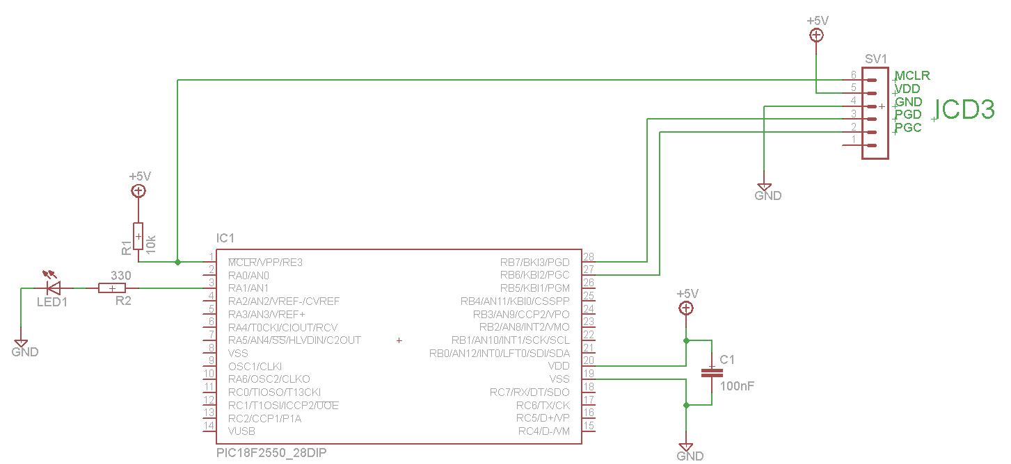
Overall, the board's design emphasizes ease of use, flexibility in power options, and a streamlined programming process, making it an effective tool for developers working with microcontroller applications.There is one switch to reset the board. When reset is held, the board is in bootloader mode waiting for an upload from the development computer for 5 seconds. After 5 seconds, the current program is run. This board can be powered by the USB connector subject to computer power limitations. It can be powered by an external power supply from 4. 2Vcc t o 5. 5Vcc. You can add an onboard regulator to provide 5V Vcc for the microcontroller chip (using a 7805 voltage regulator for example). // This is a tool to program the pinguino bootloader in a new chip // with your Pinguino, the self replicating machine!
// Jean-Pierre MANDON 2010 // Fixed bug 02/07/2011 PGM pin is no longer used #define PGC 1 // connected to the PGC pin of the blank chip #define PGD 2 // connected to the PGD pin of the blank chip #define VPP 3 // connected to the VPP pin of the blank chip #define VCC 6 // connected to the power on transistor #define redled 5 uchar bulkerase[48] ={0x00, 0x3C, 0x0E, 0x00, 0xF8, 0x6E, 0x00, 0x00, 0x0E, 0x00, 0xF7, 0x6E, 0x00, 0x05, 0x0E, 0x00, 0xF6, 0x6E, 0x0C, 0x3F, 0x3F, 0x00, 0x3C, 0x0E, 0x00, 0xF8, 0x6E, 0x00, 0x00, 0x0E, 0x00, 0xF7, 0x6E, 0x00, 0x04, 0x0E, 0x00, 0xF6, 0x6E, 0x0C, 0x8F, 0x8F, 0x00, 0x00, 0x00, 0x00, 0x00, 0x00}; uchar startwrite[24]={0x00, 0xA6, 0x8E, 0x00, 0xA6, 0x9C, 0x00, 0x00, 0x0E, 0x00, 0xF8, 0x6E, 0x00, 0x00, 0x0E, 0x00, 0xF7, 0x6E, 0x00, 0x00, 0x0E, 0x00, 0xF6, 0x6E}; uchar startwrid[24] ={0x00, 0xA6, 0x8E, 0x00, 0xA6, 0x8C, 0x00, 0x30, 0x0E, 0x00, 0xF8, 0x6E, 0x00, 0x00, 0x0E, 0x00, 0xF7, 0x6E, 0x00, 0x00, 0x0E, 0x00, 0xF6, 0x6E}; uchar checkmem[32]; uint address=0; #define pic_on() digitalWrite(VCC, LOW) #define pic_off() digitalWrite(VCC, HIGH) // begin programming mode // power is on ( VCC and Programing voltage ) void start_pgm() { digitalWrite(VPP, HIGH); delayMicroseconds(4); } // end programming mode // power is on ( VCC and Programing voltage ) void stop_pgm() { digitalWrite(PGD, LOW); digitalWrite(PGC, LOW); digitalWrite(VPP, LOW); } // send a command to the chip // SPI soft void send_command(uchar command, uchar lowbyte, uchar highbyte) { unsigned char i; for (i=0;i<4;i+) { digitalWrite(PGC, HIGH); if (command&1)=1) digitalWrite(PGD, HIGH); else digitalWrite(PGD, LOW); digitalWrite(PGC, LOW); command=command>>1; } for (i=0;i<8;i+) { digitalWrite(PGC, HIGH); if (lowbyte&1)=1) digitalWrite(PGD, HIGH); else digitalWrite(PGD, LOW); digitalWrite(PGC, LOW); lowbyte=lowbyte>>1; } for (i=0;i<8;i+) { digitalWrite(PGC, HIGH); if (highbyte&1)=1) digitalWrite(PGD, HIGH); else digitalWrite(PGD, LOW); digitalWrite(PGC, LOW); highbyte=highbyte>>1; } digitalWrite(PGC, LOW); digitalWrite(PGD, LOW); } // special end of command write // DS39622K Page 20 figure 3. 5 (Flash Microcontroller Programming Specification) void end_writecmd() { unsigned char i; digitalWrite(PGD, LOW); for (i=0;i<3;i+) { digitalWrite(PGC, HIGH); digitalWrite(PGC, LOW); } digitalWrite(PGC, HIGH); delay(6); digitalWrite(PGC, LOW); delayMicroseconds(500); for (i=0;i<8;i+) { digitalWrite(PGC, HIGH); digitalWrite(PGC, LOW); } for (i=0;i<8;i+) { digitalWrite(PGC, HIGH); digitalWrite(PGC, LOW); } } // Read Flash memory // Pinguino examples Flash folder uint ReadFlash(uint address) { uchar high8, low8; TBLPTRU=0; TBLPTRH=address>>8; TBLPTRL=address; _asm tblrd*+ _endasm; low8=TABLAT; _asm tblrd*+ _endasm; high8=TABLAT; return(high8<<8)+low8); } //- // begining of the main loop //- void setup() { pinMode(PGC, OUTPUT); digitalWrite(PGC, LOW); pinMode(PGD, OUTPUT); digitalWrite(PGD, LOW); pinMode(VPP, OUTPUT); digitalWrite(VPP, LOW); pinMode(redled, OUTPUT); digitalWrite(redled, LOW); pinMode(VCC, OUTPUT); digitalWrite(VCC, HIGH); } void loop() { int i; // erase chip pic_on(); delay(20); start_pgm(); digitalWrite(redled, HIGH); delay(10); for (i=0;i<48;i+=3) send_command(bulkerase[i], bulkerase[i+1], bulkerase[i+2]); delay(100); stop_pgm(); delay(20); pic_off(); delay(1000); // read boot
🔗 External reference
The board is utilized for programming the Pinguino bootloader onto a new chip. It includes various definitions for pin connections such as PGC, PGD, VPP, VCC, and redled, which correspond to specific pins on the microcontroller. The firmware includes arrays for bulk erase and write commands, as well as functions to manage the programming process, including starting and stopping programming mode, sending commands to the chip, and reading flash memory.
The setup function initializes the necessary pins for operation, while the loop function contains the logic for erasing the chip and programming it with new data.
The board's functionality is centered around its ability to program microcontrollers using the Pinguino bootloader, making it a versatile tool for electronics development and prototyping.
The board's reset switch serves as a critical interface for entering bootloader mode, allowing developers to upload new firmware to the microcontroller. The USB power supply option provides convenience for development environments, while the external power supply capability ensures flexibility in various applications.
The addition of a voltage regulator simplifies the power management for the microcontroller, ensuring it operates within its specified voltage range. The programming interface is designed to facilitate easy communication with the microcontroller, utilizing defined pins for command and data transfer.
The programming process is managed by a series of well-defined functions that handle the intricacies of microcontroller programming, including chip erase and data writing. The use of arrays for command sequences enhances modularity and ease of updates to the firmware.
Overall, the board's design emphasizes ease of use, flexibility in power options, and a streamlined programming process, making it an effective tool for developers working with microcontroller applications.There is one switch to reset the board. When reset is held, the board is in bootloader mode waiting for an upload from the development computer for 5 seconds. After 5 seconds, the current program is run. This board can be powered by the USB connector subject to computer power limitations. It can be powered by an external power supply from 4. 2Vcc t o 5. 5Vcc. You can add an onboard regulator to provide 5V Vcc for the microcontroller chip (using a 7805 voltage regulator for example). // This is a tool to program the pinguino bootloader in a new chip // with your Pinguino, the self replicating machine!
// Jean-Pierre MANDON 2010 // Fixed bug 02/07/2011 PGM pin is no longer used #define PGC 1 // connected to the PGC pin of the blank chip #define PGD 2 // connected to the PGD pin of the blank chip #define VPP 3 // connected to the VPP pin of the blank chip #define VCC 6 // connected to the power on transistor #define redled 5 uchar bulkerase[48] ={0x00, 0x3C, 0x0E, 0x00, 0xF8, 0x6E, 0x00, 0x00, 0x0E, 0x00, 0xF7, 0x6E, 0x00, 0x05, 0x0E, 0x00, 0xF6, 0x6E, 0x0C, 0x3F, 0x3F, 0x00, 0x3C, 0x0E, 0x00, 0xF8, 0x6E, 0x00, 0x00, 0x0E, 0x00, 0xF7, 0x6E, 0x00, 0x04, 0x0E, 0x00, 0xF6, 0x6E, 0x0C, 0x8F, 0x8F, 0x00, 0x00, 0x00, 0x00, 0x00, 0x00}; uchar startwrite[24]={0x00, 0xA6, 0x8E, 0x00, 0xA6, 0x9C, 0x00, 0x00, 0x0E, 0x00, 0xF8, 0x6E, 0x00, 0x00, 0x0E, 0x00, 0xF7, 0x6E, 0x00, 0x00, 0x0E, 0x00, 0xF6, 0x6E}; uchar startwrid[24] ={0x00, 0xA6, 0x8E, 0x00, 0xA6, 0x8C, 0x00, 0x30, 0x0E, 0x00, 0xF8, 0x6E, 0x00, 0x00, 0x0E, 0x00, 0xF7, 0x6E, 0x00, 0x00, 0x0E, 0x00, 0xF6, 0x6E}; uchar checkmem[32]; uint address=0; #define pic_on() digitalWrite(VCC, LOW) #define pic_off() digitalWrite(VCC, HIGH) // begin programming mode // power is on ( VCC and Programing voltage ) void start_pgm() { digitalWrite(VPP, HIGH); delayMicroseconds(4); } // end programming mode // power is on ( VCC and Programing voltage ) void stop_pgm() { digitalWrite(PGD, LOW); digitalWrite(PGC, LOW); digitalWrite(VPP, LOW); } // send a command to the chip // SPI soft void send_command(uchar command, uchar lowbyte, uchar highbyte) { unsigned char i; for (i=0;i<4;i+) { digitalWrite(PGC, HIGH); if (command&1)=1) digitalWrite(PGD, HIGH); else digitalWrite(PGD, LOW); digitalWrite(PGC, LOW); command=command>>1; } for (i=0;i<8;i+) { digitalWrite(PGC, HIGH); if (lowbyte&1)=1) digitalWrite(PGD, HIGH); else digitalWrite(PGD, LOW); digitalWrite(PGC, LOW); lowbyte=lowbyte>>1; } for (i=0;i<8;i+) { digitalWrite(PGC, HIGH); if (highbyte&1)=1) digitalWrite(PGD, HIGH); else digitalWrite(PGD, LOW); digitalWrite(PGC, LOW); highbyte=highbyte>>1; } digitalWrite(PGC, LOW); digitalWrite(PGD, LOW); } // special end of command write // DS39622K Page 20 figure 3. 5 (Flash Microcontroller Programming Specification) void end_writecmd() { unsigned char i; digitalWrite(PGD, LOW); for (i=0;i<3;i+) { digitalWrite(PGC, HIGH); digitalWrite(PGC, LOW); } digitalWrite(PGC, HIGH); delay(6); digitalWrite(PGC, LOW); delayMicroseconds(500); for (i=0;i<8;i+) { digitalWrite(PGC, HIGH); digitalWrite(PGC, LOW); } for (i=0;i<8;i+) { digitalWrite(PGC, HIGH); digitalWrite(PGC, LOW); } } // Read Flash memory // Pinguino examples Flash folder uint ReadFlash(uint address) { uchar high8, low8; TBLPTRU=0; TBLPTRH=address>>8; TBLPTRL=address; _asm tblrd*+ _endasm; low8=TABLAT; _asm tblrd*+ _endasm; high8=TABLAT; return(high8<<8)+low8); } //- // begining of the main loop //- void setup() { pinMode(PGC, OUTPUT); digitalWrite(PGC, LOW); pinMode(PGD, OUTPUT); digitalWrite(PGD, LOW); pinMode(VPP, OUTPUT); digitalWrite(VPP, LOW); pinMode(redled, OUTPUT); digitalWrite(redled, LOW); pinMode(VCC, OUTPUT); digitalWrite(VCC, HIGH); } void loop() { int i; // erase chip pic_on(); delay(20); start_pgm(); digitalWrite(redled, HIGH); delay(10); for (i=0;i<48;i+=3) send_command(bulkerase[i], bulkerase[i+1], bulkerase[i+2]); delay(100); stop_pgm(); delay(20); pic_off(); delay(1000); // read boot
🔗 External reference
Related Circuits
The LED blinks as expected, then pauses for an indefinite duration, flashes again a different number of times, and turns off again, displaying no discernible cyclic behavior. It activates without any external input, indicating that there is likely no...
The analog to digital converter (ADC) is commonly required in most of the projects. Analog voltage measurement can be done using the ADC hardware built in together in a PIC. The picture below shows a simple setup for measuring...