
Pico ammeter
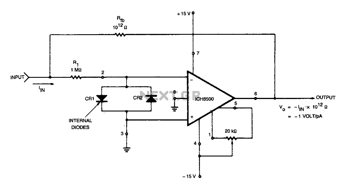
To ensure optimal performance in electronic circuits, particularly those involving current summation, it is crucial to eliminate the influence of stray currents at the current summing node. This is achieved by equalizing the potential of all points surrounding the input to the same level as the input itself, which is set to a virtual ground (0V). The grounding of the device's case serves a dual purpose: it not only stabilizes the input potential but also intercepts any stray leakage currents that may arise between the ±15V input terminals and the inverting input summing junctions.
In designing circuits with high-speed response requirements, minimizing feedback capacitance is essential. Excessive capacitance can slow down the circuit's response to input signals, particularly when subjected to step function input currents. The time constant, a critical factor in determining the speed of the circuit's response, is calculated as the product of the feedback capacitance (C) and the feedback resistor (R). For example, if the feedback capacitance is set at 1pF, the resulting time constant would be 1 second. It is important to note that the circuit will take approximately 5 seconds, which corresponds to five time constants, to stabilize within 1% of its final output voltage after a step function input current is applied.
Achieving a feedback capacitance value below 0.3pF necessitates careful circuit layout and design considerations. This involves optimizing the physical arrangement of components to minimize parasitic capacitance and ensuring that the feedback path is as short as possible. By adhering to these principles, the circuit can achieve rapid stabilization and maintain high fidelity in the presence of fast-changing input signals.Care must be taken to eliminate any stray currents from flowing into the current summing node. This can be accomplished by forcing all points surrounding the input to the same potential as the input. In this case the potential of the input is at virtual ground, or OV. Therefore, the case of the device is grounded to intercept any stray leakage currents that may otherwise exist between the ±15 V input terminals and the inverting input summing junctions.
Feedback capacitance should be kept to a minimum in order to maximize the response time of the circuit to step function input currents. The time constant of the circuit is approximately the produce of the feedback capacitance C^ times the feedback resistor R^. For instance, the time constant of the circuit is I sec if C^, = lpF. Thus, it takes approximately 5 sec (5 time constants) for the circuit to stabilize to within 1% of its final output voltage after a step function of input current has been applied.
of less than 0.2 to 0.3 pF can be achieved with proper circuit layout. 🔗 External reference
Related Circuits
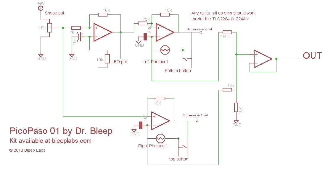
It is similar to the Atari Punk synth, also known as Forrest Mims' stepped tone generator, but utilizes two triangle wave oscillators that can be combined or used independently. A wave shaper and square wave LFO are employed to...
This multimeter is designed to measure output voltage and current in a power supply unit (PSU), with the current sense shunt resistor connected in series with the load at the negative voltage rail. It operates using a single supply...
The 1N4001 is a 1 Amp silicon rectifier with a voltage range of 50 to 1000 volts. It features guaranteed high-temperature soldering, high current capability, a diffused junction, low reverse leakage, and utilizes a void-free molded plastic technique for...
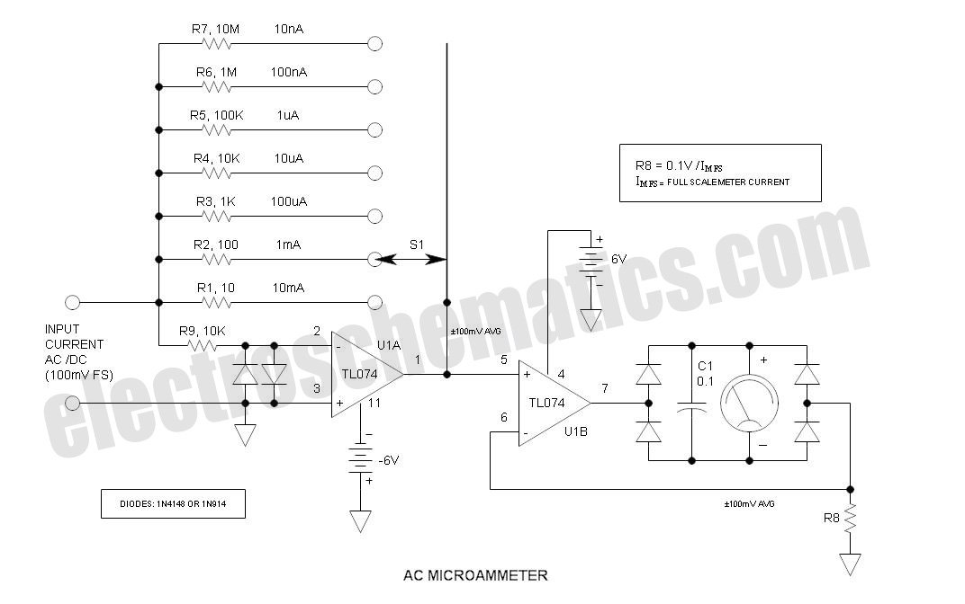
This is a variation of Mr. Marian's "Simple Micro Ampere Meter Circuit" that employs active circuitry and an analog meter to measure sensitive DC currents. The circuit in question is designed to provide precise measurements of very low DC currents,...
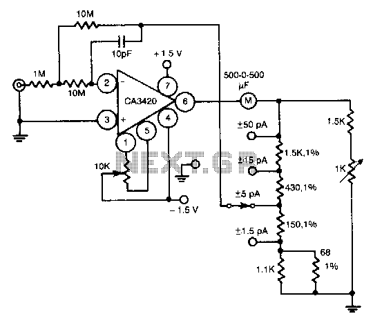
This circuit utilizes the exceptionally low input current of 0.1 pA from the CA3420 BiMOS operational amplifier. It employs a single 10-MΩ resistor. The circuit operates within a range of ±50 pA, achieving a maximum full-scale sensitivity of ±1.5...
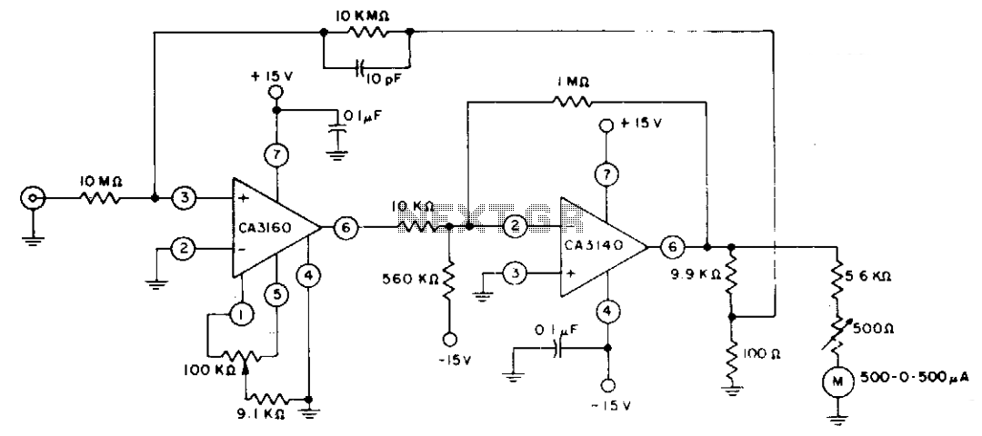
The circuit employs CA3160 and CA3140 BiMOS operational amplifiers to achieve a full-scale meter deflection of ±3 pA. The CA3140 functions as a 1T0 gain stage, supplying the necessary positive and negative output swing for the meter and the...