
PIERCE CRYSTAL OSCILLATOR

The JFET Pierce oscillator is a versatile circuit that leverages the properties of a Junction Field Effect Transistor (JFET) to generate a stable oscillation signal. The core of the circuit typically consists of a JFET configured in a common-source arrangement, which is coupled with a feedback network that includes passive components such as resistors and capacitors. This configuration allows the circuit to achieve a high degree of frequency stability, making it suitable for applications requiring precise timing signals.
In microprocessor applications, the JFET Pierce oscillator can provide a reliable clock signal essential for synchronizing the internal operations of the chip. This clock signal is critical for ensuring that all components of the microprocessor operate in harmony, thus enabling efficient processing and data management.
For digital timepieces and calculators, the oscillator's simplicity and stability make it an ideal choice. It can produce a frequency that corresponds to the required timekeeping precision, ensuring accurate time display and calculation functions.
The capability to use the JFET Pierce oscillator as an injection oscillator is particularly valuable for troubleshooting purposes. By connecting a probe to the output, technicians can inject the oscillator's frequency into a circuit under test. This allows for the identification of faults or performance issues within the system, facilitating efficient diagnostics.
Furthermore, when a small length of wire is attached to the output, the oscillator can be transformed into a micropower transmitter. This configuration enables the transmission of low-power signals over short distances, which can be useful in various applications, including remote sensing and wireless communication systems. The simplicity of the design allows for easy integration into compact devices, making it a popular choice among electronics engineers for low-power transmission tasks.
Overall, the JFET Pierce oscillator stands out for its stability, ease of use, and adaptability, making it a fundamental component in modern electronic applications.The JFET Pierce oscillator is stable and simple. It can be the clock of a microprocessor, a digital timepiece or a calculator. With a probe at the output, it can be used as a precise injection oscillator for troubleshooting. Attach a small length of wire at the output and this circuit becomes a micropower transmitter.. 🔗 External reference
Related Circuits
A basic Wien Bridge Oscillator utilizes a filament lamp in conjunction with an operational amplifier (op-amp). The property of filament lamps, specifically the non-linear increase in resistance of the tungsten filament as it heats, plays a crucial role in...
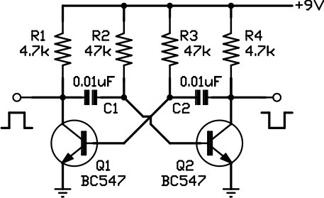
This circuit is one of the simplest to implement but can be challenging to comprehend. It consists of a two-transistor oscillator known as an astable multivibrator, which generates a square wave output that is out of phase. Initially, it...
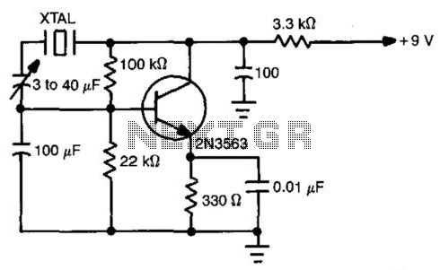
This simple circuit will oscillate with a wide range of crystals. Connect several different types of crystal holders in parallel to improve versatility. The 3 to 40 pF capacitor adjusts crystal frequency over a small range for setting to...
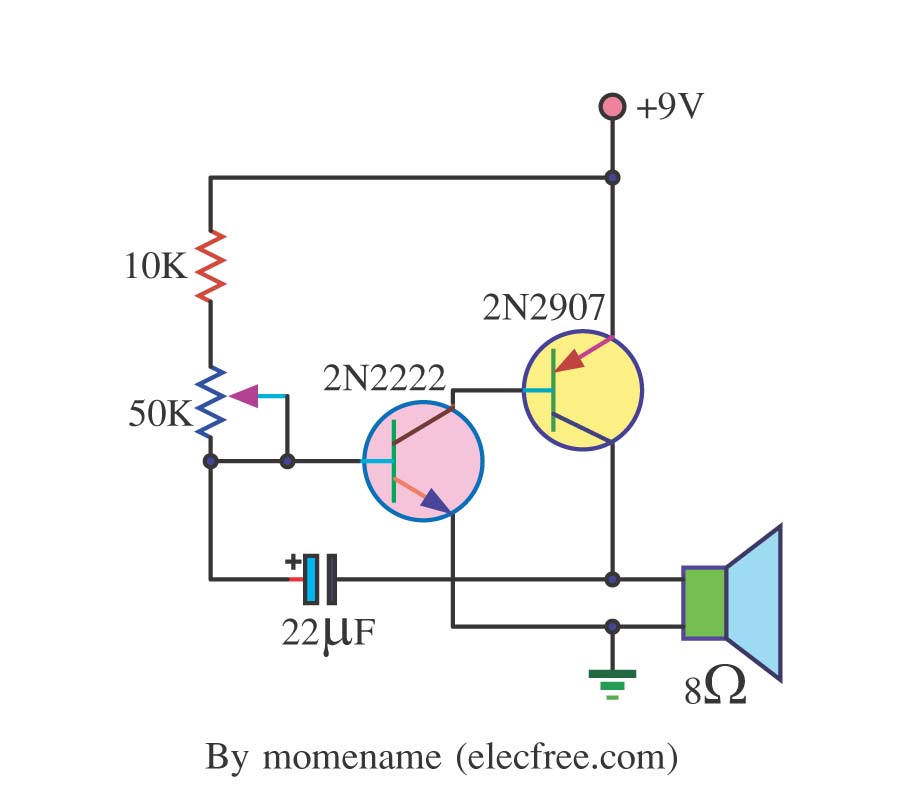
This is a simple tone oscillator generator. It uses the transistors 2N2222 and 2N2907 as the main components. The tone sound is controlled with a 50K ohm resistor (R2) and an 8-ohm speaker is utilized. The tone oscillator generator circuit...
Its frequency depends on the capacitance of the vary cap diode. The center frequency is changed by varying the biasing voltage of the vary cap through the 47K pot. You can use a 75cm telescopic antenna or simply a...
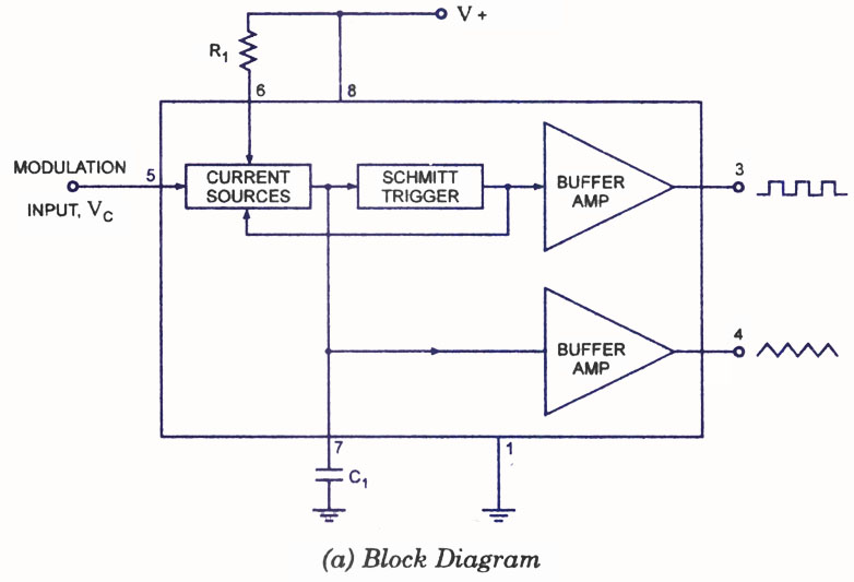
A voltage-controlled oscillator (VCO) is a type of oscillator in which the frequency of output oscillations can be adjusted by varying the amplitude of an input voltage signal. VCOs are commonly utilized in frequency modulation (FM), pulse modulation (PM),...