
Colpitts oscillator FM transmitter

The circuit described utilizes a variable capacitance diode (varicap) to modulate frequency, which is a common approach in RF applications. The frequency output is contingent upon the capacitance of the varicap, which is influenced by the biasing voltage applied through a variable resistor, specifically a 47K potentiometer. This allows for fine-tuning of the center frequency, facilitating adjustments based on the desired operational parameters.
For antenna selection, the circuit can accommodate a 75 cm telescopic antenna, although a simple length of hook-up wire may suffice for effective transmission. The reported performance indicates a range of approximately 100 meters when using a 6 cm hook-up wire, demonstrating the circuit's efficiency in typical FM applications.
The coil is an essential component in this design and can be fabricated directly onto a printed circuit board (PCB) using copper tracks. The dimensions for the coil should be accurately transferred to the copper board, followed by an etching process to create the desired coil structure. If the specified 1 mm spacing between tracks poses a challenge, a sharp blade can be employed to manually remove excess copper, ensuring proper coil formation.
Alternatively, a square spiral coil may be constructed using copper wire, adhering to the provided dimensions. It is important to note that slight deviations from the specified dimensions are acceptable, allowing for some flexibility in the design process. Additionally, experimentation with an 18 SWG copper wire coil consisting of five turns and a diameter of 5 mm is suggested. The center tap for this coil can be taken from either the second or third turn, providing further options for tuning and performance optimization. Such configurations can enhance the adaptability of the circuit to various operational contexts. Its frequency depends on the capacitance of the vary cap diode. The center frequency is changed by varying the biasing voltage of the vary cap through the 47K pot. You can use a 75cm telescopic antenna or simply a length of hook-up wire. Mine worked fine with a 6cm hook-up wire and gave a range of 100m with a good FM receiver. The coil shown below can be constructed on the PCB itself as PCB track. Just transfer the dimensions on a copper board and etch it. If the 1mm spacing is difficult use a sharp blade to remove unwanted copper. You can also use a copper wire and construct a square spiral of the dimensions shown below. Please note that a small deviation from the given dimensions is permissible. Note: You can even try a coil made of 18SWG copper wire of 5 turns and 5mm dia with air core. The center tap can then be taken at the 2nd or 3rd turn.( I have'nt tried it tell me if it works well). 🔗 External reference
Related Circuits
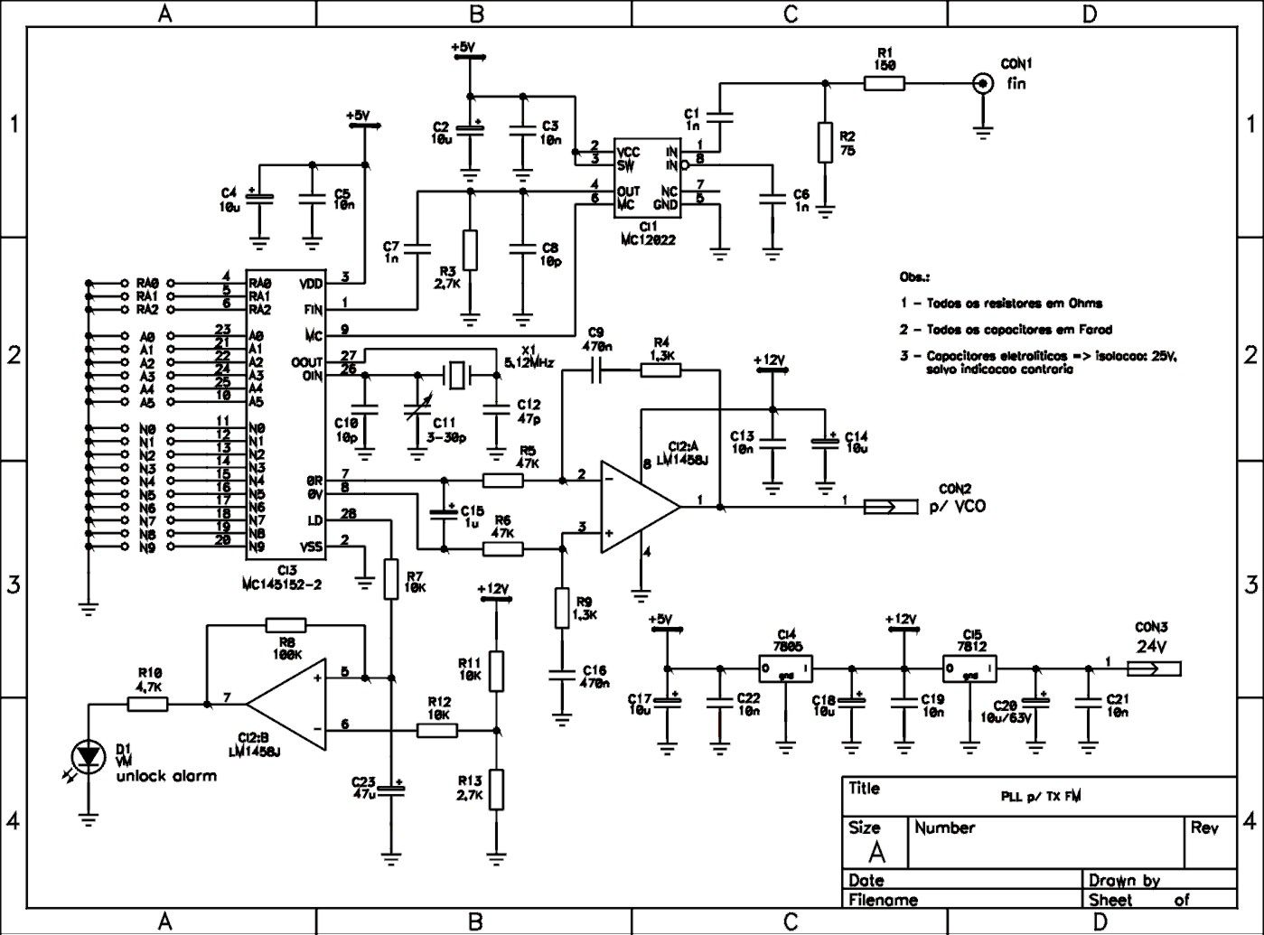
This is a schematic of a synthesized Phase-Locked Loop (PLL) for a low-power FM transmitter. It can also be utilized with other circuits, provided that the loop filter response, components, VCO tank circuit, and appropriate thumbswitch programming keys and...
The range of this FM transmitter is approximately 100 meters when powered by a 9V DC supply. The circuit consists of three main stages. The first stage is a microphone preamplifier utilizing a BC548 transistor. The second stage features...
AM Transmitter. It is illegal to operate a radio transmitter without a license in most countries. This circuit is deliberately limited in power output. An AM transmitter is designed to modulate an audio signal onto a carrier wave for the...
Electronics tutorial about the 555 oscillator and how the 555 oscillator can be used as a 555 astable oscillator circuit to generate square wave waveforms. The 555 timer IC is a versatile and widely used component in electronics, particularly for...
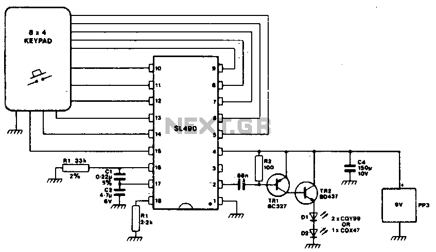
This simple infrared transmitter uses the PPM output from pin 2 of the SL490, which is connected to the base of the PNP transmitter TR1. It generates an amplified current pulse approximately 15 microseconds wide. This pulse is further...
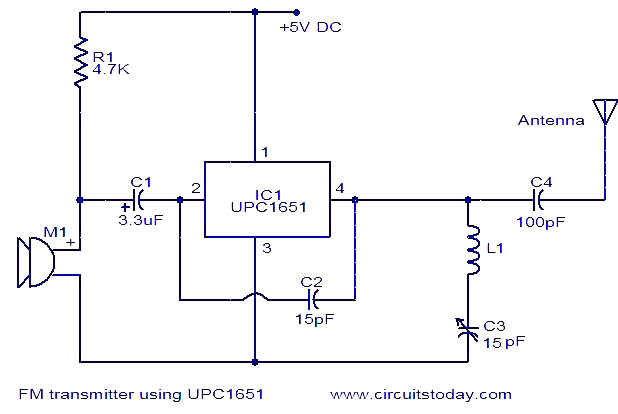
The circuit diagram of an FM transmitter utilizes the IC UPC1651, which is a wideband UHF Silicon MMIC amplifier. This integrated circuit features a broad frequency response of up to 1200 MHz and a power gain of up to...