
Pierce Crystal Oscillator Design
The Pierce oscillator is a type of electronic oscillator that utilizes a common emitter amplifier configuration, integrating a quartz crystal to achieve stable frequency oscillation. The circuit typically consists of a bipolar junction transistor (BJT) configured as a common emitter amplifier, which provides the necessary gain for oscillation. The collector load is formed by a tuned circuit, often comprising an inductor (L) and a capacitor (C), which together resonate at the desired frequency.
The quartz crystal acts as a frequency-selective element, ensuring that the oscillator operates at its fundamental frequency. This is critical for maintaining stability and precision in applications such as clock generation and signal processing. The feedback from the output to the input through the crystal is essential for satisfying the Barkhausen criteria, which states that the product of gain and feedback must equal one at the frequency of oscillation.
To analyze the performance of the Pierce oscillator, the AC equivalent circuit is drawn, which simplifies the assessment of the loop gain. This equivalent circuit typically includes the transistor's small-signal model, the tuned circuit, and the crystal's impedance characteristics. By calculating the loop gain at the oscillation frequency, one can confirm whether the conditions for sustained oscillation are met.
In practical implementations, additional components such as biasing resistors and coupling capacitors may be included to stabilize the operating point of the transistor and to ensure proper signal coupling between stages. The design considerations for the Pierce oscillator also involve selecting the appropriate values for the inductance and capacitance in the tuned circuit to match the crystal's resonant frequency, thus optimizing the oscillator's performance.The Pierce oscillator shown above is essentially a common emitter amplifier with a tuned circuit for a collector load and a quartz crystal as a feedback element. In order to determine whether the Barkhausen criteria is satisfied, loop gain must be determined at the frequency of oscillation.
This is accomplished by drawing the AC equivalent circuit of the Pierce Oscillator as shown below. 🔗 External reference
Related Circuits
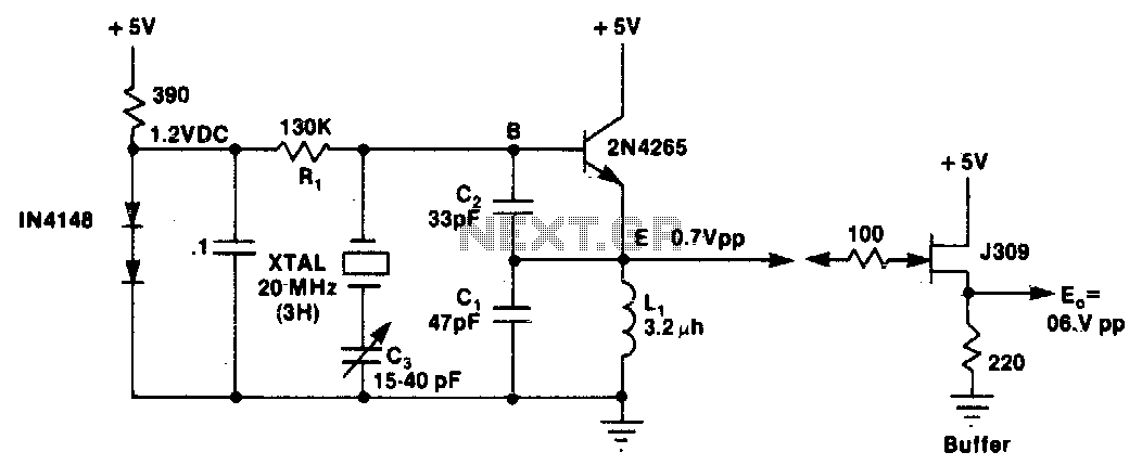
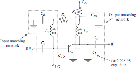
L1 and C1 are selected to resonate at a frequency below the desired crystal harmonic but above the crystal's next lower odd harmonic. Capacitor C2 should have a value between 30-70 pF, independent of the oscillation frequency. There is...
The intersection of industry and data collection systems includes hydrometeorological control systems, robot control systems, and digital image transmission systems. This is facilitated by the electron transport of data information. The data transmission system is a crucial component of...
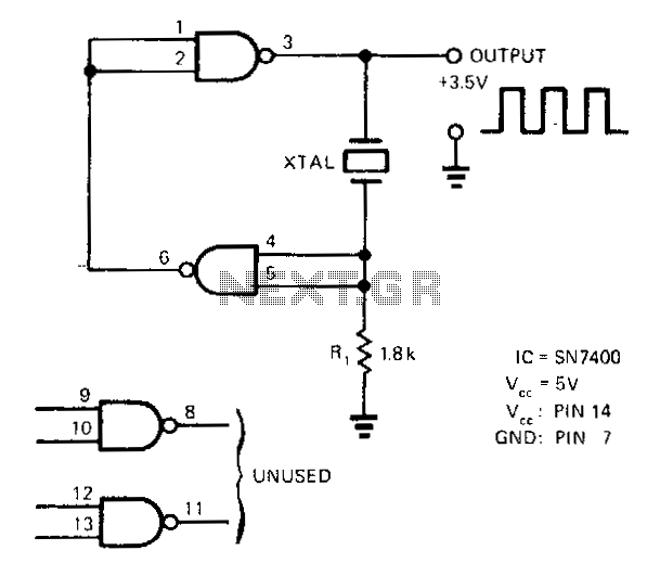
A SN7400 quartz crystal and a resistor provide a square-wave output of approximately 3.5 V. The circuit operates reliably at frequencies from 120 kHz to 4 MHz. The circuit utilizes a SN7400 integrated circuit, which is a quad two-input NAND...
The emergence of modern radio and radar systems has created a demand for stable harmonic oscillations at specific carrier frequencies to facilitate the necessary modulation and mixing conditions. While early carrier frequencies primarily operated in the low to mid...

Due to the amplifier's frequency characteristics and the impact of parasitic capacitance, designing an active filter that operates effectively at hundreds of kilohertz is quite challenging. Additionally, since the circuit consists of a low-pass filter with a large coil...
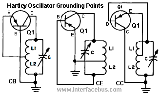
A Hartley Oscillator is a type of oscillator that utilizes two series-connected inductors or an inductor with a center-tapped coil, along with a capacitor. The tank circuit is created by the inductor and the parallel capacitor. An oscillator circuit...