
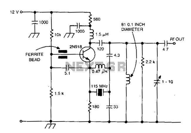
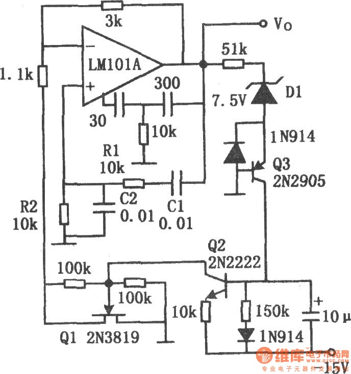
Colpitts harmonic oscillator 100Mhz

In this circuit design, the resonant components L1 and C1 are crucial for establishing the desired oscillation frequency. The selection of L1 and C1 ensures that the resonance occurs at a frequency that is strategically placed below the intended crystal harmonic, thereby allowing for effective operation while avoiding interference from the next lower odd harmonic. The specified range for C2, between 30-70 pF, is designed to maintain a stable oscillation frequency across varying conditions, ensuring reliable performance of the oscillator circuit.
The choice of C1 relative to C2 is flexible; however, it is recommended that C1 be approximately 1-3 times the capacitance of C2 to achieve optimal performance in harmonic circuits. This relationship helps to stabilize the oscillation and improve the efficiency of the circuit.
The inclusion of diodes D1, D2, and D3 serves to create a regulated bias supply, which is essential for maintaining consistent voltage levels throughout the circuit. This regulation helps to mitigate fluctuations that could adversely affect the performance of the oscillator.
Furthermore, the resistance of R1 plays a significant role in determining the quality factor (Q) of the crystal when it is in-circuit. A higher resistance value for R1 is advantageous as it enhances the Q factor, leading to sharper resonance and improved selectivity in frequency response. This is particularly important in applications where precision frequency control is required.
Overall, this circuit configuration is designed to optimize the performance of the crystal oscillator by carefully selecting component values and configurations to achieve desired operational characteristics.L1C1 are selected to be resonant at a frequency below the desired crystal harmonic but above the crystal"s next lower odd harmonic. C2 should have a value of 30-70 pF, independent of the oscillation frequency. There is no requirement for any specific ratio of C1/C2, but practical harmonic circuits seem to work best when Cl is approximately 1-3 times the value of C2.
Diodes D1-D3 provide a simple regulated bias supply The resistance of Rl should be as high as possible, as it affects the crystal"s in-circuit Q.
Related Circuits
This design is intended for high reliability across a broad temperature range utilizing fifth and seventh overtone crystals. The inductor connected in parallel with the crystal induces antiresonance of crystal capacitance (Co) to reduce loading effects. This technique is...
Using two gates from a CMOS 4011 NAND chip, a simple square wave oscillator can be made. Alternatively, a CMOS 4001 chip can also be used, or a TTL equivalent. In this circuit, the mark-space ratio can also be...
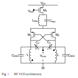
The oscillator is designed to tune from 1.8 GHz to 2 GHz for typical cellular telephony applications. An extended tuning range can be obtained by adjusting the ratio between the varactor capacitance and fixed capacitance in the tank. PMOSFETs...
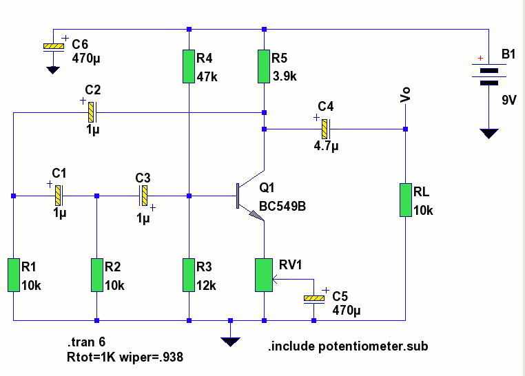
The circuit is a standard RC phase shift oscillator that utilizes a single bipolar transistor as the active component. When power is supplied, regenerative feedback is applied through capacitor C2 from the collector to the base of the transistor....
The chart illustrates the Wien bridge sine wave oscillator circuit. The amount of negative feedback in the circuit is determined by the internal resistance of the FET. When the peak output voltage of the oscillator reaches the regulated voltage...
The generators of square pulses are used in a lot of applications, including the adjustment of conditions of entry in digital circuits and the control of acoustic frequency amplifiers. This circuit is a generator that produces, in combination with...