
Pilot 505 amp

The Pilot 505 amplifier is a vintage audio device that employs a tube-based design, which is characteristic of high-fidelity sound reproduction. The circuit is primarily built around five 5AR4 rectifier tubes, which are responsible for converting AC voltage from the power supply into DC voltage, essential for the operation of the amplifier's circuitry. The use of multiple 5AR4 tubes indicates a robust power supply design, capable of delivering the necessary current for the amplifier's operation.
The amplifier's output stage consists of four EL84 tubes, known for their warm sound and efficiency in producing audio signals. These tubes are configured in a push-pull arrangement, which enhances the output power while minimizing distortion. The EL84 tubes are typically biased in a class AB configuration, allowing for a balance between efficiency and sound quality.
Additionally, the circuit incorporates two 12AX7 tubes in the preamplifier section. These tubes are renowned for their high gain and low noise characteristics, making them ideal for amplifying weak audio signals before they are sent to the output stage. The design likely includes tone control and volume adjustment features, allowing the user to tailor the sound to their preference.
The absence of a schematic diagram may pose challenges for repairs or modifications, as understanding the interconnections between components and the overall circuit layout is crucial for effective troubleshooting. It is advisable to seek out forums or communities dedicated to vintage audio equipment, as members may have access to the desired schematic or could provide insights based on their experiences with similar models.I have looked in all the usual places and can`t seem to find one? Pilot 505. It has a 5AR 4,-4-,EL84`s-and 2, 12AX7`s. Thanks for any help you may.. 🔗 External reference
Related Circuits
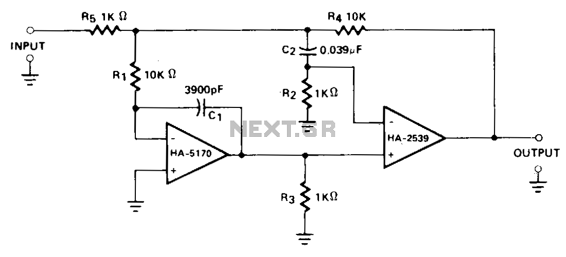
A composite configuration significantly reduces errors without compromising the high-speed, wideband characteristics of the HA-2539. The HA-2540 can also be utilized, although it exhibits slightly lower speeds and bandwidth response. The HA-2539 amplifies signals above 40 kHz, which are...
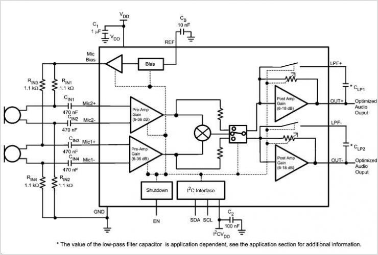
Figure 1 illustrates the schematic for a universal input, 7.6 V, 700 mA constant voltage/constant current (CV/CC) power supply designed for LED driver applications. This design employs the LinkSwitch-II product LNK606PG in a flyback configuration. The LNK606PG (U1) integrates...
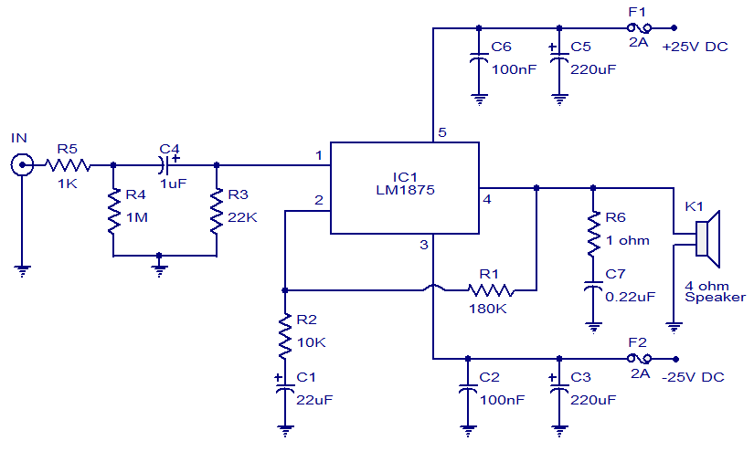
This weblog focuses on electronic circuit schematics, PCB design, DIY kits, and electronic project diagrams. The featured project is a 20W audio amplifier circuit based on the LM1875 audio amplifier IC from National Semiconductors. With a 25V power supply,...
This low-noise microphone amplifier is built with the MAT02 produced by PMI. This microphone amplifier is highly efficient and features a very low noise level. The amplification can be set to either 20 dB or 23.5 dB (10x or...
A 1000 Watts audio power amplifier circuit designed for outdoor use. A circuit diagram is needed urgently to facilitate the construction of this high-power amplifier, which is a personal passion project. The design of a 1000 Watts audio power amplifier...
The circuit was designed according to the RIAA implementation of a Hi-Fi phono preamplifier for the purpose of reproducing audio from a moving magnet cartridge. The RIAA (Recording Industry Association of America) equalization curve is essential for the accurate playback...