
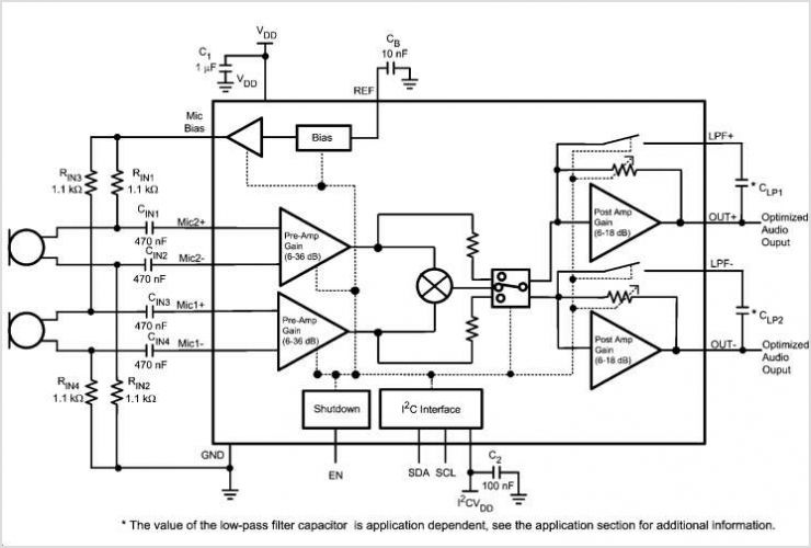
LMV1090 Dual Input Far Field Noise Suppression Microphone Amplifier
The schematic depicted in Figure 1 serves as a robust framework for a power supply tailored for LED applications, balancing performance with regulatory compliance. The use of the LNK606PG IC streamlines the design process by incorporating multiple functions into a single chip, which minimizes the component count and simplifies the overall layout. The diode bridge formed by D1 to D4 is crucial for converting the AC input into a usable DC output, while the filtering action of capacitors C1 and C2 ensures a stable voltage free from ripple, which is essential for sensitive LED drivers.
The inclusion of inductors L1 and L2 not only aids in noise attenuation but also plays a pivotal role in energy storage and transfer within the flyback topology, enhancing efficiency. The damping resistors R1 and R2 mitigate potential oscillations that could arise from the interaction between the inductors and capacitors, thereby stabilizing the output voltage and current characteristics of the power supply.
The design's compliance with EMI standards is particularly noteworthy, as it demonstrates a commitment to minimizing interference with other electronic devices. The E-Shield technology employed in the transformer design is an innovative approach that effectively reduces EMI emissions without the additional complexity and cost of incorporating a Y capacitor.
Inrush current limiting through the fusible resistor RF1 is a critical safety feature, protecting the circuit from potential damage during startup conditions. Additionally, the constant current capability of the LNK606PG allows for seamless operation under varying load conditions, ensuring that the LED loads receive consistent current even as they may change over time. The overvoltage protection feature further enhances the reliability of the system, safeguarding against unexpected failures that could lead to open circuits in the LED array.
Overall, the schematic provides a comprehensive solution for LED driver applications, emphasizing efficiency, safety, and compliance with industry standards.Figure 1 shows the schematic for a universal input, 7. 6 V, 700 mA CV/CC power supply for LED Driver applications, using the LinkSwitch-II product LNK606PG in a‚ flyback con guration. The LNK606PG (U1) combines a power switching device, Oscillator CV/CC control engine, and startup and protection functions in one IC.
Diodes D1 through D4 rectify the AC input. Capacitors C1 and C2 lter the recti ed AC. In combination with inductors L1 and L2, these capacitors also attenuate conducted differential-mode EMI noise. Resistors R1 and R2 dampen any resulting resonant ringing between capacitors and inductors. This con guration, along with Power Integrations` transformer E-Shield technology, ensures meeting EMI standard EN55015 class B with >10 dB margin, using no Y capacitor.
Fusible resistor RF1 limits inrush current at startup, and fuses if any component fails from excess input current. This power supply design uses the inherent CC feature of U1 to drive LED loads and CAN operate at maximum power output in CC mode.
IC U1`s CV mode provides output overvoltage protection if an LED should have an open-circuit failure. 🔗 External reference
Related Circuits
The video amplifier depicted in the diagram is a widely recognized design that is both simple and highly effective. However, the transistors are susceptible to damage if the potentiometers (black level and signal amplitude) are set to their extreme...
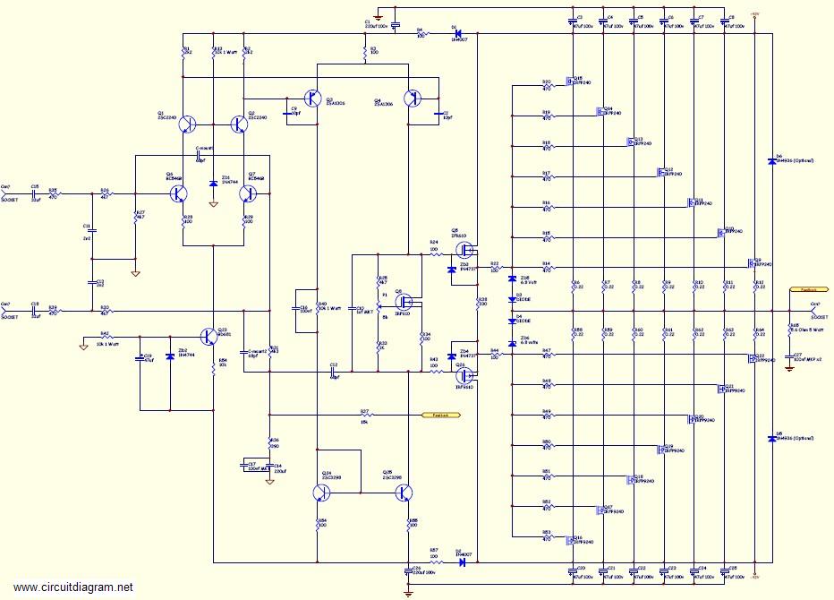
This amplifier is suitable for various applications that demand high power, low noise, minimal distortion, and superior sound quality. Examples include subwoofer amplifiers, front-of-house (FOH) stage amplifiers, and individual channels of high-powered surround sound amplifiers. For a detailed explanation...
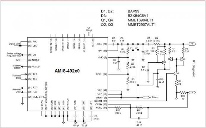
The AMU2481 Audio Mixer is a digital real-time signal processor utilizing NMOS technology, available in a 24-pin DIL plastic package or a 44-pin PLCC package. It is designed for the digital processing of both TV audio information and digital...
The following circuit illustrates a 10.7 MHz RF amplifier and filter circuit diagram. Features include significant capacitances of a power MOSFET. The 10.7 MHz RF amplifier and filter circuit is designed to amplify radio frequency signals while simultaneously filtering out...
This circuit enables the display of an ECG signal on an oscilloscope. Operational amplifiers IC1a, IC1b, and IC1d create an instrumentation amplifier with a gain of 201. IC1c amplifies the common-mode signal by a factor of 31 and supplies...
To complement the 60 Watt MOSFET audio amplifier, a high-quality preamplifier design was necessary. A discrete components topology utilizing ±24V supply rails was selected, with an emphasis on minimizing the transistor count while achieving low noise, very low distortion,...
Warning: include(partials/cookie-banner.php): Failed to open stream: Permission denied in /var/www/html/nextgr/view-circuit.php on line 713
Warning: include(): Failed opening 'partials/cookie-banner.php' for inclusion (include_path='.:/usr/share/php') in /var/www/html/nextgr/view-circuit.php on line 713