
Motor speed control circuit
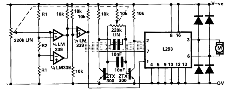
The modified bi-directional proportional motor control circuit addresses the inherent limitation of continuous motor movement when the potentiometer is centered. The original circuit's reliance on a single potentiometer made it difficult to achieve a precise 1:1 mark-space ratio, leading to undesired motor creep.
In this enhanced design, a second potentiometer is employed, effectively ganged with the first. This configuration allows for better control over the motor's behavior by providing an additional adjustment mechanism. The second potentiometer is strategically connected between the power supply lines, enabling it to create a voltage reference that can be monitored by a window comparator.
The window comparator serves a critical role in this circuit modification. It compares the voltage levels from the second potentiometer against predefined thresholds. When the voltage from the second potentiometer falls within a specific range, the window comparator activates the inhibit input of the L293 motor driver. This action effectively cuts off the drive signal to the motor, preventing it from creeping when the primary potentiometer is near its center position.
The L293 motor driver is a dual H-bridge driver that allows for bi-directional control of DC motors. By integrating the window comparator with the L293, the circuit achieves a more stable and responsive motor control system. The combination of these components ensures that the motor can be accurately stopped when the potentiometer is adjusted to the center position, enhancing the overall functionality and performance of the motor control circuit.
In summary, this modified circuit design significantly improves the usability of the bi-directional proportional motor control system by incorporating an additional potentiometer and a window comparator, effectively addressing the creeping issue and ensuring precise motor control.A shortcoming of the above bi-directional proportional motor control circuit is that with the potentiometer in its center position the motor does not stop, but creeps due to the difficulty in setting the potentiometer for an exact 1:1 mark-space ratio from the flip-flop. This modified circuit uses a second potentiometer, ganged with the first used to inhibit drive to the motor near the center position.
This potentiometer is connected between the supply lines and feeds a window comparator which in turn drives the inhibit input of the L293. 🔗 External reference
Related Circuits
This project allows for the control of two wheels or tracks from a PC serial port without any wired connections. The system operates at 2400 baud. A Basic Stamp microcontroller is utilized, with the Basic Stamp I being used...
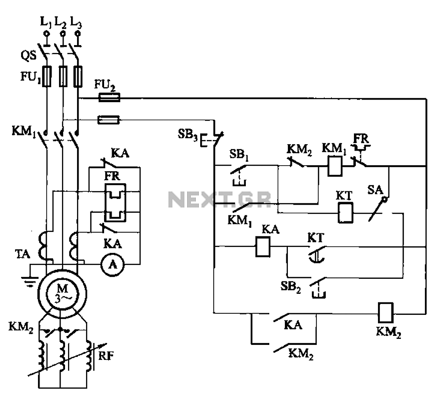
The circuit shown in Figure 3-164 can operate in both manual and automatic modes. During startup, the normally closed contact of relay KA is shorted, which affects the heating element to avoid prolonged startup times that could lead to...
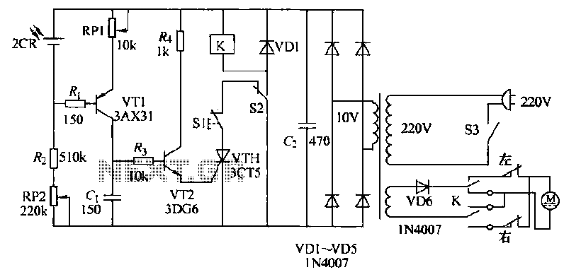
The circuit operates as follows: each morning, light enters the silicon photocell, generating a force that causes transistor VT1 to conduct. As a result, capacitor C charges, leading to an increase in voltage. This rising voltage causes the emitter...
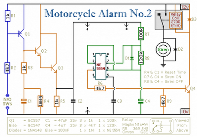
Any number of normally-open switches may be utilized. Install "tilt" switches that close when the steering is moved or when the bike is lifted off its side-stand or pushed forward off its centre-stand. Employ micro-switches to secure removable panels...
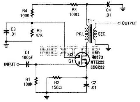
A MOSFET is utilized as a wideband buffer amplifier. T1 is wound on a toroid of approximately specified diameter, using material suitable for the frequency range, typically between 1 MHz and 20 MHz. The turns ratio should be approximately...
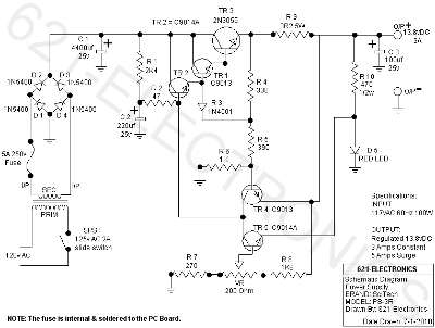
The following circuit illustrates the SciTech PS-3R Power Supply Circuit. Features include 13.8V DC output, 5 Amps surge capability, and a constant output of 3 Amps. Components include a transistor and others. The SciTech PS-3R Power Supply Circuit is designed...