
PIR Sensor Based Security System circuit diagramworkingapplications
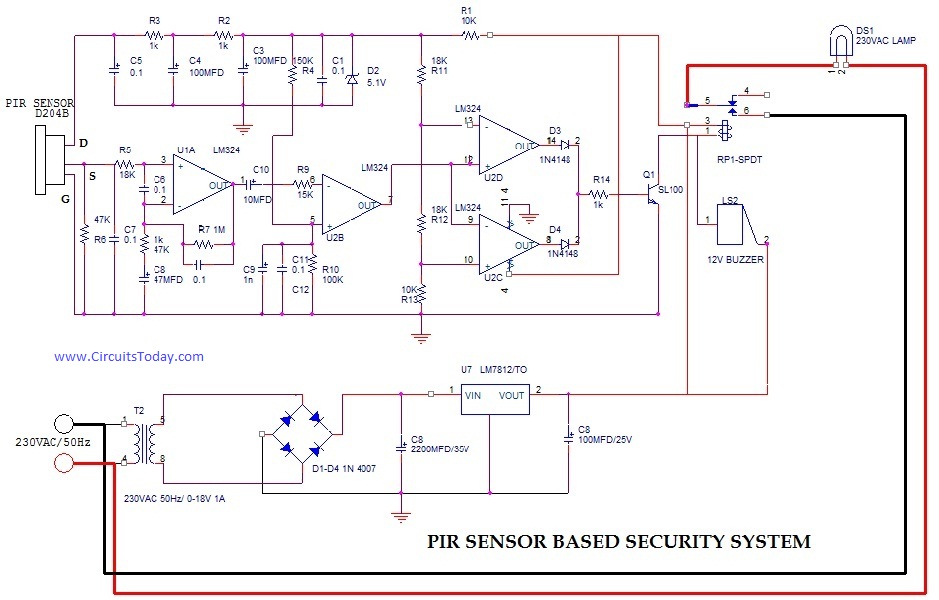
The PIR (Passive Infrared) sensor-based security system is designed to detect motion by measuring changes in infrared radiation emitted by objects in its vicinity, particularly warm bodies such as humans and animals. The system typically consists of a PIR sensor, a microcontroller or processing unit, and an alert mechanism such as an LED or alarm.
In a typical circuit diagram, the PIR sensor is connected to the power supply and interfaced with a microcontroller, which processes the sensor's output. The PIR sensor outputs a digital signal when motion is detected, which is fed into one of the microcontroller's input pins. The microcontroller is programmed to respond to this input by activating an alert mechanism.
Applications of this system are widespread, including residential security, commercial surveillance, and automation systems. The PIR sensor can be integrated into alarm systems, automated lighting controls, and other smart home devices, enhancing security and energy efficiency.
The circuit design may include additional components such as resistors, capacitors, and diodes to ensure proper functioning and stability. A common configuration involves using a resistor to limit current to the sensor and a capacitor to filter noise from the power supply. The microcontroller may also interface with other sensors or modules, such as cameras or GSM modules, to provide comprehensive monitoring and alert capabilities.
Overall, the PIR sensor-based security system represents an effective solution for detecting unauthorized access and ensuring safety in various environments.PIR (Passive Infrared Radial) Sensor Based Security System, circuit diagram,working,applications.. 🔗 External reference
Related Circuits
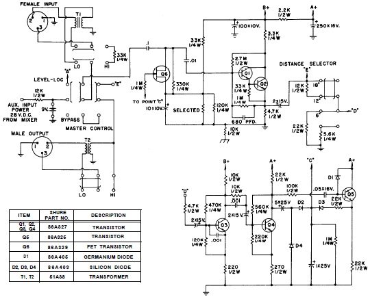
SHURE is an American corporation that manufactures consumer and professional audio electronics, including microphones, phonograph cartridges, and discussion systems. SHURE Incorporated is a well-established entity in the audio electronics industry, recognized for its innovative design and high-quality products. The company...
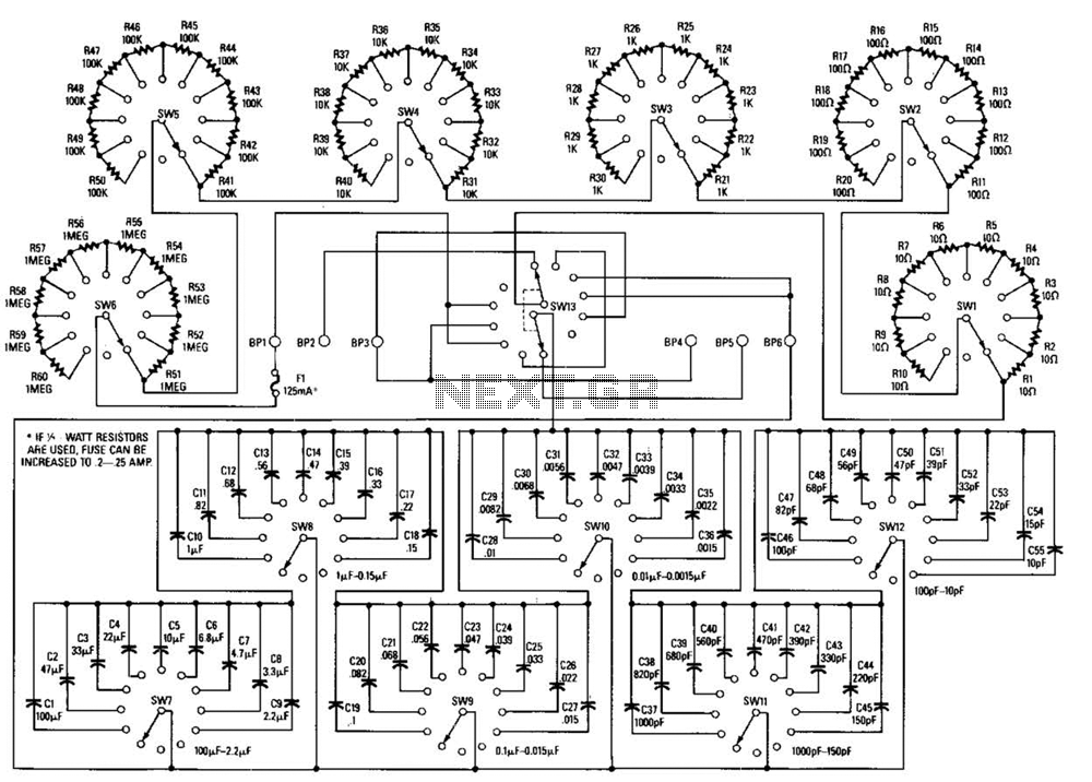
This decade box can be configured for any resistance value between 10 and 11.1 in 10-stop increments. A switch is employed to set various RC configurations. It is recommended to utilize precision components in the circuit. If feasible, verify...
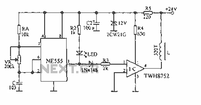
The device is designed to accelerate the defrosting process of fish, meat, and other foods by utilizing audio vibrations. This method allows for defrosting in warm water, significantly reducing the time required compared to conventional methods, while preserving the...
The TX05C-R infrared surveillance alarm circuit is designed for monitoring walls, windows, doors, and various restricted areas. When an intrusion occurs, the alarm activates to enhance security. The circuit comprises a transmitter module, a receiver module, a time-base circuit,...
This universal battery charger utilizes the LM317 voltage regulator and features an adjustable output voltage along with a constant-current charging circuit, making it suitable for charging most NiCad batteries and various other battery types. The LM317 universal battery charger...

The current design of a power inverter offers an efficiency of approximately 85% and a power output exceeding 200 watts. This document provides a complete circuit schematic and detailed building procedure for a home-built power inverter. While numerous articles...