
Rc Decade Box Circuit
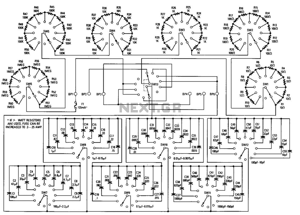
This decade box circuit serves as a versatile tool for experimenting with various resistance values and RC configurations. The design allows for a range of resistance settings, enabling users to select increments of 10 ohms, providing flexibility for testing and calibration purposes. The inclusion of a switch for configuration selection enhances usability, allowing for quick transitions between different circuit setups.
Precision is crucial in this circuit; therefore, high-tolerance components are essential to maintain the integrity of the resistance values and the performance of the RC configurations. An accurate bridge should be employed to validate the component values, ensuring that the decade box operates within the desired specifications.
The configurations available through switch S13 allow for multiple applications. The resistor-only configuration is ideal for applications requiring a fixed resistance, while the capacitor-only configuration allows for capacitance testing. The series RC configuration is useful for analyzing the behavior of resistors and capacitors in series, while the parallel RC configuration is beneficial for studying parallel combinations. The low-pass filter configuration can be utilized to allow signals below a certain frequency to pass while attenuating higher frequencies, making it suitable for audio applications and signal processing. Conversely, the high-pass filter configuration permits signals above a certain frequency to pass, effectively blocking lower frequencies.
The terminal numbers BP1 to BP6 facilitate easy connections for external components, ensuring that users can quickly set up their experiments or applications. Each binding post corresponds to specific points in the circuit, enabling straightforward access to the various configurations and enhancing the overall functionality of the decade box. This decade box can be set for any resistance value between 10 and 11.1 in 10- stops. A switch can be used to configure several RC configurations. Use close tolerance components in the circuit. If possible, check components with-an accurate bridge or other means to ensure accuracy. THE VARIOUS CONFIGURATIONS are set using S13: (a) resistor only and (b) capacitor only (both in position r/c); (c) series RC (position ser); (cy parallel RC (position par); (e) Low-Pass filter (position lpf); and (f) High-Pass Filter (position hpf). The terminal numbers listed are those of bindinq-posts BP1-BP6. 🔗 External reference
Related Circuits
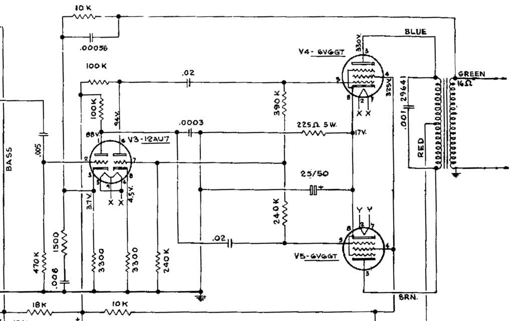
This schematic has been modified from an old Bell & Howell projector amplifier for model 302, utilizing PP 6V6 tubes with a 12AU7 phase inverter (PI). The PI circuit appears to be closest to a "floating paraphase." There is...
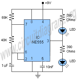
A project of a 555 tester circuit, the circuit will start blinking LEDs when power is applied, which will indicate that the IC is working correctly. The 555 tester circuit is designed to verify the operational status of the 555...
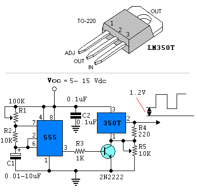
Power pulse circuit using LM350 and NE555. This circuit can be used to drive lamps, power LEDs, DC motors, etc. Adjust R5 for output amplitude and R1 for output power. The LM350 is an adjustable 3-terminal voltage regulator. The power...
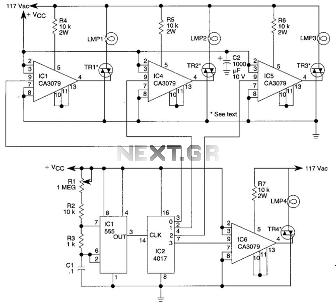
A 555 timer (IC1) controls a 4017 CMOS decade counter. The first four outputs of the 4017 drive a CA3079 zero-voltage switch. Pin 9 of the CA3079 is utilized to inhibit output from pin 4, effectively disabling the stream...
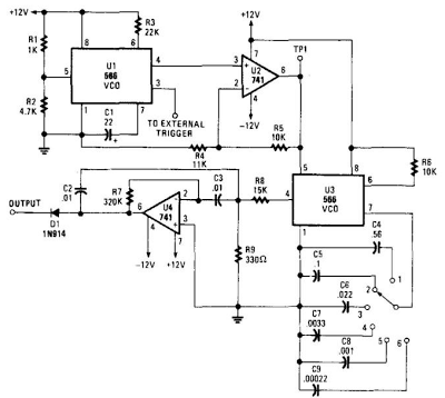
When this circuit is connected to a filter and an oscilloscope, the oscilloscope displays the filter's frequency response. A frequency that sweeps from low to high is applied to a filter. The oscilloscope is triggered by the start of...
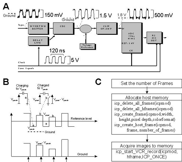
This document provides technical details regarding the hardware and software of a complete imaging system that utilizes a fast CCD sensor and a 41 Msample/s A/D converter. This system is capable of acquiring full-frame digitized images at a resolution...