
playback amplifier for cassette
The described circuit operates as a playback amplifier for cassette tapes, utilizing a two-stage amplification process to enhance the audio signal generated by the playback head. The initial stage, A1, is responsible for applying RIAA equalization to the audio signal, which is essential for accurate reproduction of recorded material. This equalization process compensates for the frequency response characteristics of tape recording, ensuring that the playback is faithful to the original sound.
The integration of a double-pole switch allows for flexibility in supporting various tape types, including the more sensitive chromium dioxide tapes, which require specific adjustments to the amplification characteristics. The passive high-pass filter, implemented using components C3 and R5, effectively reduces low-frequency rumble, enhancing overall sound quality by eliminating unwanted noise below the cut-off frequency.
The circuit's design emphasizes simplicity and efficiency, as it can be constructed on a compact PCB and housed within the cassette deck enclosure. This compactness is particularly advantageous for portable applications. The symmetrical power supply configuration ensures stability and minimizes the risk of signal distortion during operation.
In summary, this playback amplifier circuit is engineered to deliver high-quality audio reproduction from cassette tapes, leveraging RIAA equalization and effective filtering to maintain sound fidelity while accommodating different tape types. The overall design is both practical and efficient, making it suitable for integration into various audio systems.For some time now, there have been a number of tape cassette decks available at low prices from mail order businesses and electronics retailers. Such decks do not contain any electronics, of course. It is not easy to build a recording amplifier and the fairly complex magnetic biasing circuits, but a playback amplifier is not too difficult as the p
resent one shows. The stereo circuits in the diagram, in conjunction with a suitable deck, form a good-quality cassette player. The distortion and frequency range (up to 23 kHz) are up to good standards. Moreover, the circuit can be built on a small board for incorporation with the deck in a suitable enclosure.
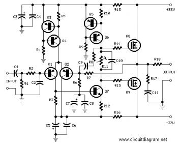
Both terminals of coupling capacitor C1 are at ground potential when the amplifier is switched on. Because of the symmetrical ±12 V supply lines, the capacitor will not be charged. If a single supply is used, the initial surge when the capacitor is being charged causes a loud click in the loudspeaker and, worse, magnetizes the tape. The playback head provides an audio signal at a level of 200 500 mV. The two amplifiers raise this to line level, not linearly, but in accordance with the RIAA equalization characteristic for tape recorders.
Broadly speaking, this characteristic divides the frequency range into three bands: Between 50 Hz and 1. 326 kHz, corresponding to a time constant of 120 µs, for normal tape, or 2. 274 kHz, corresponding to a time constant of 70 µs, for chromium dioxide tape, the signal is amplified at a steadily decreasing rate.
Above 1. 326 kHz or 2. 274 kHz, as the case may be, the signal is slightly and linearly amplified. This characteristic is determined entirely by A1 (A1`). To make the amplifier suitable for use with chromium dioxide tape, add a double-pole switch (for stereo) to connect a 2. 2 k resistor in parallel with R3 (R3`). The output of A1 (A1`) is applied to a passive high-pass rumble filter, C3-R5 (C3`-R5`) with a very low cut-off frequency of 7 Hz.
The components of this filter have exactly the same value as the input filter, C1-R1 (C1`-R1`). The second stage, A2 (A2`) amplifies the signal 100, that is, to line level (1V r. m. s. ). 🔗 External reference
Related Circuits
High-quality amplifier for headphones electronics project. No need for preamplifier. Circuit diagram. The described project involves the design of a high-quality headphone amplifier that operates without the necessity of a preamplifier stage. This simplifies the circuit while still delivering superior...
This circuit can be directly connected to CD players, tuners, and tape recorders. It requires the addition of a 10K logarithmic potentiometer (dual gang for stereo) and a switch to accommodate various sources. Proper grounding is crucial to eliminate...
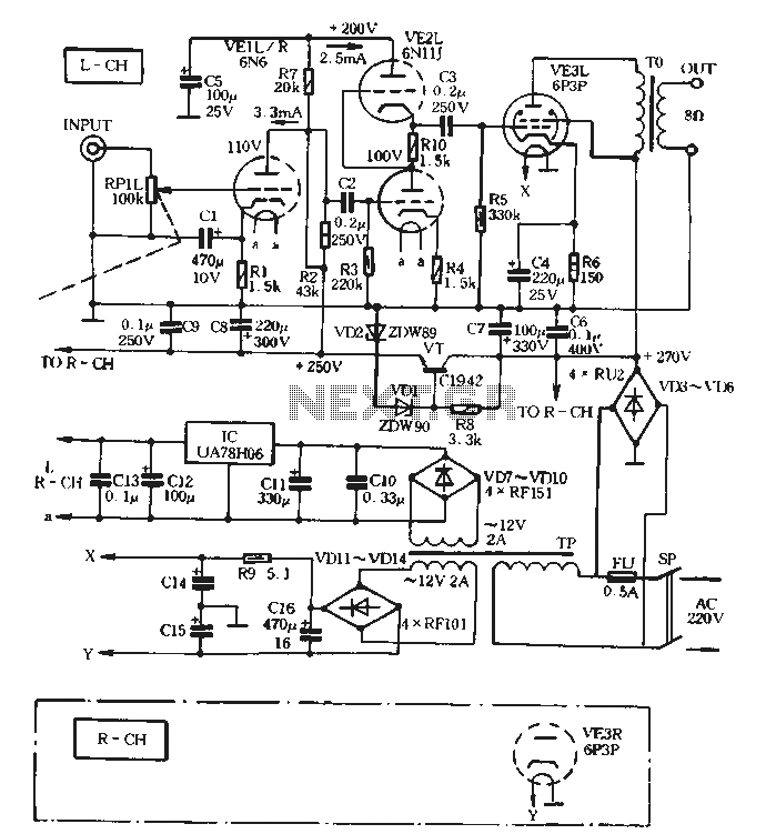
The VE1 preamplifier utilizes a low muscle, low resistance double triode 6N6 configuration, with separate halves for the left and right audio channels. The design operates within the CPI framework. It promotes the use of high-level VE2 household low...
The output devices are MJL4281A (NPN) and MJL4302A (PNP), and feature high bandwidth, excellent SOA (safe operating area), high linearity and high gain. Driver transistors are MJE15034 (NPN) and MJE15035 (PNP). All devices are rated at 350V, with the power...
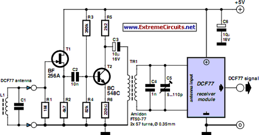
A popular project among microcontroller enthusiasts is to build a radio-controlled clock. Tiny receiver boards are available, equipped with a pre-adjusted ferrite antenna, which receive and demodulate the DCF77 time signal broadcast from Mainflingen in Germany. The DCF77 signal...
This is a circuit diagram of an audio amplifier circuit featuring a 10W power amplifier using the TDA2003 integrated circuit from SGS Thomson. The IC is capable of delivering 10W into a 4-ohm load at a supply voltage of...