
PlayPIC
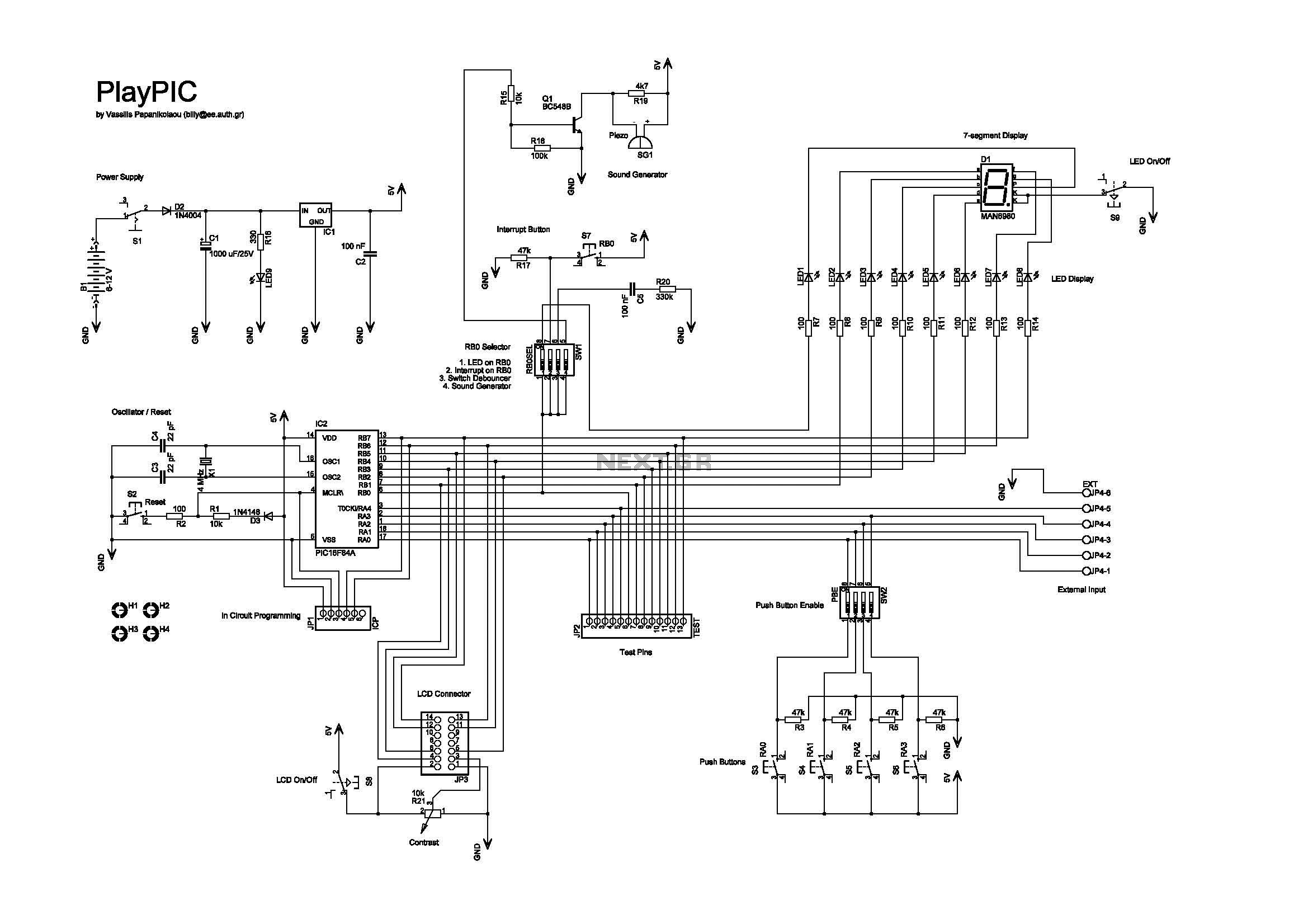
The tutorial board designed around the PIC16F84A microcontroller serves as a versatile platform for beginners in microcontroller programming and experimentation. The board incorporates eight individual LEDs, which provide visual feedback for the user, and a 7-segment display that enhances the capability to present numerical data. The 7-segment display is directly connected to the LEDs, with segments corresponding to LEDs 2 through 8 (RB1 to RB7) and the decimal point linked to LED1 (RB0). This configuration allows for seamless integration of the display with the interrupt switch S7, enabling it to function effectively during programming exercises.
The board is equipped with five push buttons, which can be utilized for various input operations, allowing users to interact with the microcontroller in real time. The in-circuit programming (ICP) header facilitates easy reprogramming of the microcontroller without the need to remove it from the circuit, streamlining the development process. The programmer used must support the ICP feature, such as the OziPic er, to ensure compatibility.
Furthermore, the board includes a 6-screw external input connector (JP4) designed for pins RA0 to RA4. When this connector is engaged, it is essential to deactivate the corresponding input switches (S3 to S6) using switch SW2 to prevent conflicts in input readings. The last screw terminal is designated for ground, providing a common reference point for the circuit.
To ensure proper functionality during programming, it is crucial to disconnect the LCD module from its socket, as indicated in the provided instructions. This precaution helps avoid potential conflicts or errors during the programming process, ensuring a smooth experience for users as they explore the capabilities of microcontroller programming.This is a new design of a tutorial board based on the popular PIC16F84A microcontroller. It features eight single leds, a 7-segment display, an LCD display and five push buttons. It is an ideal solution for the beginner to take his/her first programming steps in the world of microcontrollers. Having an in-circuit-programming (ICP) header, it can b e easily reprogrammed without unplugging the microcontroller each time, provided that the programmer also supports this feature (like OziPic er). - The 7-segment display is always connected to the individual leds. Its seven segments correspond to LED2 to LED8 (RB1 to RB7) and the decimal dot to LED1 (RB0). This correspondence enables the 7-segment display to work together with the interrupt switch S7, which is connected to RB0.
- JP4 is an 6-screw external input connector for RA0-RA4. When used, the corresponding input switches S3-S6 must be turned off by SW2. Last screw is ground. The top photo shows the in-circuit-programming procedure with the help of an appropriate programmer (like OziPic`er) which features an ICP header. In order for the procedure to work correctly, the LCD module has to be disconnected from its socket during programming.
🔗 External reference
Related Circuits

This is a new design of a tutorial board based on the popular PIC16F84A microcontroller. It features eight single LEDs, a 7-segment display, an LCD display, and five push buttons. It is an ideal solution for beginners to take...
The new design of a tutorial board based on the popular PIC16F84A microcontroller features eight single LEDs, an LCD display, and five push buttons. The tutorial board designed around the PIC16F84A microcontroller serves as a versatile platform for educational purposes...

This is a new design of a tutorial board based on the popular PIC16F84A microcontroller. It features eight single LEDs, a 7-segment display, an LCD display, and five push buttons. It is an ideal solution for the beginner to...

The new design of a tutorial board based on the popular PIC16F84A microcontroller features eight single LEDs, an LCD display, and five push buttons. The tutorial board designed around the PIC16F84A microcontroller serves as an educational platform for learning and...

This is a new design of a tutorial board based on the popular PIC16F84A microcontroller. It features eight single LEDs, a 7-segment display, an LCD display, and five push buttons. It is an ideal solution for beginners to take...