
PLL IR LASER LIGHT RECEIVER
The 555-based Phase-Locked Loop (PLL) laser light Pulse Frequency Modulation (PFM) receiver circuit is designed to capture and demodulate signals from a laser light source. This circuit utilizes a 555 timer IC configured in astable mode to generate a clock signal that is phase-locked to the incoming modulated light signal.
The primary components of the circuit include the 555 timer, a photodiode or phototransistor for light detection, and passive components such as resistors and capacitors. The inclusion of a 10-kΩ precision potentiometer in place of R4 allows for precise adjustments to the center frequency of the transmitter, providing flexibility in tuning for optimal performance. This adjustment is critical in applications where frequency drift may occur due to environmental changes or component tolerances.
The capacitor C1 plays a significant role in determining the circuit's high-frequency response. By varying the capacitance value, one can optimize the circuit for different modulation frequencies, enhancing the receiver's ability to accurately demodulate the incoming signal. It is advisable to experiment with various capacitor values to find the optimal configuration that minimizes distortion and maximizes fidelity in the received signal.
Overall, this 555-based PLL laser light PFM receiver circuit is a versatile solution for applications requiring the reception of modulated laser signals, with the ability to fine-tune critical parameters for improved performance. The design's simplicity, combined with the potential for customization through component substitution, makes it suitable for both experimental setups and practical implementations in communication systems.Circuit schematics for the 555-based PLL laser light PFM receiver. Although R4 is shown as a resistor, you might want to sub-stitute it with a 10-k? precision potentiometer so that you can dial in the center frequency of the transmitter. Experiment with the value of C1 for the best high-frequency response. Notice that circuit is functionally identical to.. 🔗 External reference
Related Circuits
This project is a PLL synthesized FM radio which can decode DTMF. The receiving frequency can be set by the PLL circuit from 80-140MHz. The receiver is VERY stable, high sensitivity and easy to build and tune. The FM...
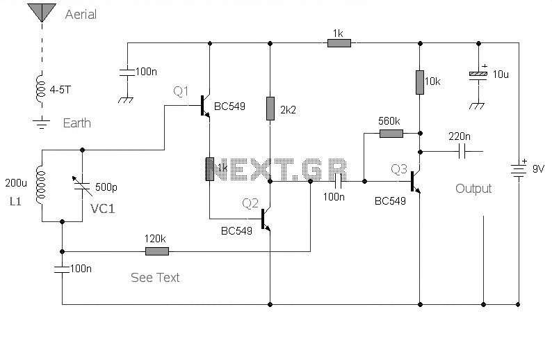
This is the circuit diagram of a mini AM radio receiver. All general-purpose transistors should work in this circuit; BC549 transistors can be used. The circuit utilizes a compact three-transistor regenerative receiver with fixed components. The mini AM radio receiver...
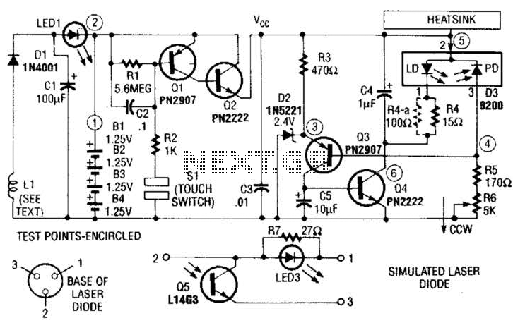
A laser diode TOLD9200 (Toshiba) serves as a source of laser light. Q3, Q2, and SI constitute a touch switch to control the laser. L1 is an RF pickup coil designed to extract energy from an RF-type battery charger....
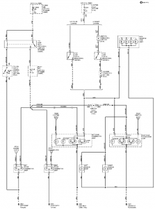
The connection and wiring between each part and component of the exterior lighting system of the vehicle includes elements such as the fusible link, junction block, tail light relay, cruise control, stop light switch, relay box, column switch, rear...
This chapter contains circuit diagrams for several power supplies for pulsed solid-state lasers. These include units suitable for driving the popular Hughes ruby and YAG rangefinder laser assemblies, one utilizing the flash from a disposable pocket camera, and a...
Dodge Durango Fog Light Wiring Diagram. The Dodge Durango fog light wiring diagram provides a visual representation of the electrical connections and components involved in the fog light system of the vehicle. This diagram typically includes the battery, fog light...
Warning: include(partials/cookie-banner.php): Failed to open stream: Permission denied in /var/www/html/nextgr/view-circuit.php on line 713
Warning: include(): Failed opening 'partials/cookie-banner.php' for inclusion (include_path='.:/usr/share/php') in /var/www/html/nextgr/view-circuit.php on line 713