
PLL SINGLE TONE DECODER
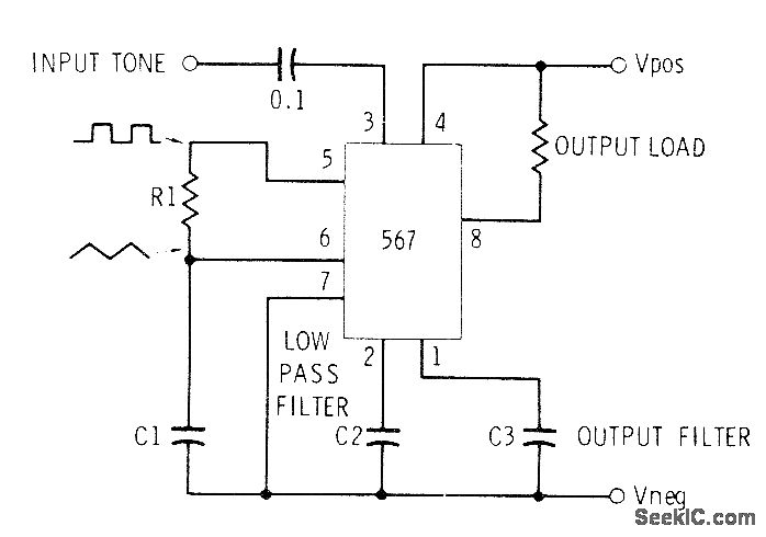
This circuit design is intended for applications involving Touch-Tone decoding and control of telephone lines or wireless systems, employing audio frequencies for operation. The selection of components is crucial for achieving the desired performance.
The center frequency of the circuit is primarily influenced by the values of the components H1 (which may refer to an inductor or other frequency-determining element) and C1 (a capacitor). The resistor R1 plays a significant role in defining the time constant of the circuit, with its resistance value required to be set between 2KΩ and 20KΩ. This range allows for flexibility in tuning the circuit’s response characteristics.
The capacitance C1 is calculated based on the relationship f = 1/R1C1, which indicates that the frequency (f) is inversely proportional to the product of the resistance (R1) and the capacitance (C1). This formula enables the designer to determine the appropriate capacitance value needed to achieve the desired frequency of operation, with C1 expressed in microfarads.
Additionally, C2 serves as a low-pass filter, which is essential for removing high-frequency noise from the signal. The value of C2 can be selected from a range of 1µF to 22µF; increasing the capacitance will result in a narrower bandwidth, thus enhancing the filtering capability of the circuit. This aspect is particularly important in applications where signal clarity is paramount.
C3, while not critical to the circuit’s operation, should be approximately twice the value of C2. This component may be used for additional stability or filtering, but its specific value can be adjusted based on the overall design requirements and performance objectives.
In summary, this circuit is designed for efficient audio frequency signal processing and control applications. The careful selection of resistors and capacitors, as outlined, ensures optimal performance in Touch-Tone decoding and related functionalities.Can be used for Touch-Tone decoding as well as for telephone-line and wireless control applications using single audio frequency. Operating center frequency depends on H1 and C1. R1 should be between 2K and 20K. C1 in microfarads is computed from f = 1/R1C1, where R is in megohms and f is in hertz. C2 is low-pass filter in range of 1-22 F; the la rger its value, the narrower its bandwidth. C3 is not critical and can be about twice C2. -C. D. Rakes, "Integrated Circuit Projects, " Howard W. Sams, Indianapolis, IN, 1975, p 68-73. 🔗 External reference
Related Circuits
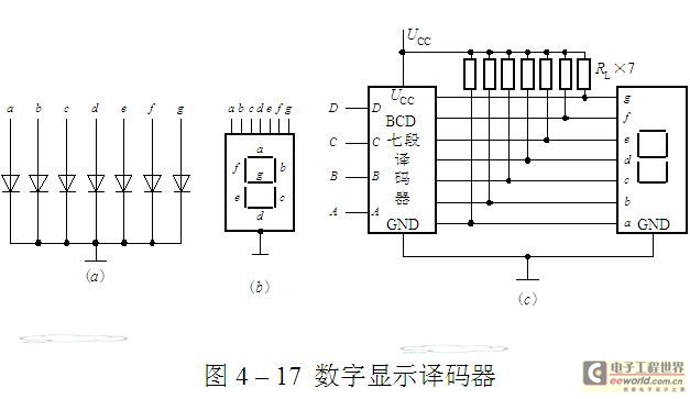
The luminescent diode (LED) is constructed from gallium arsenide (GaAs), a specialized semiconductor material, and gallium arsenide phosphide. It can be used individually or assembled into segment-type or lattice LED display devices. The display unit consists of a sectional...
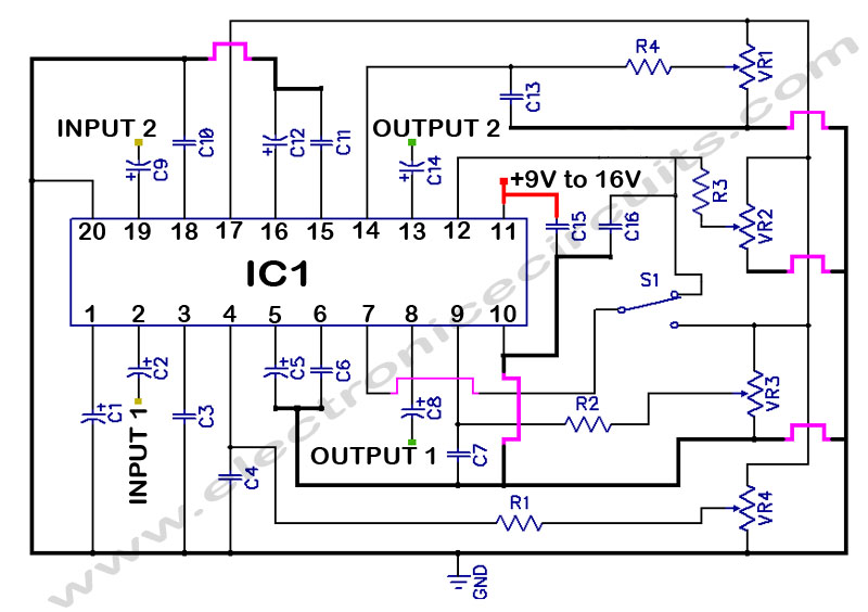
LM1036 Stereo Tone (Bass, Treble, Volume, Loudness, Balance) Controller Circuit. The LM1036 is a DC controlled tone (bass/treble), volume, and loudness controller designed for audio applications. The LM1036 circuit serves as an integrated solution for controlling various aspects of audio...
Quartz crystals exhibit a property where their amplitude and phase characteristics repeat at uneven multiples of their fundamental frequency. Overtone crystals are specifically cut to enhance this property. Any crystal can be utilized at one or more of its...
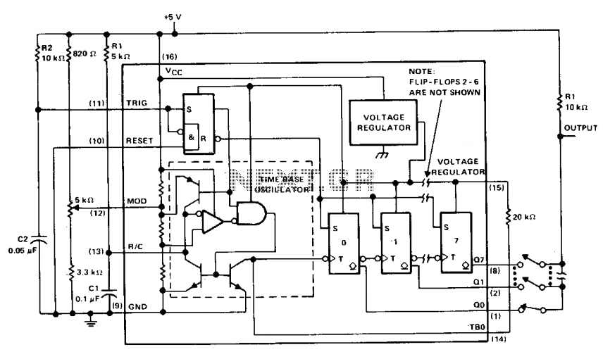
The µA2240 consists of four basic circuit elements: (1) a time-base oscillator, (2) an eight-bit counter, (3) a control flip-flop, and (4) a voltage regulator. The basic frequency of the time-base oscillator (TBO) is set by the external time...
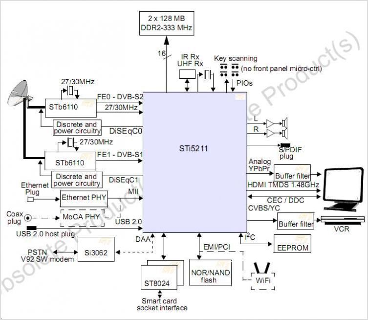
The STI7167 utilizes advanced process technology to deliver a fully featured HD AVC DVB-C and DVB-T demodulator and decoder integrated circuit (IC). This highly integrated system-on-chip is designed for set-top box (STB) markets across cable, terrestrial, and terrestrial/IP hybrid...
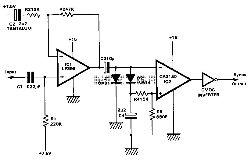
This circuit extracts the synchronization pulses from a video signal across a wide range of amplitudes and operates on a single +15 V supply. IC1 buffers and amplifies the incoming signal and applies it via C3 to the peak...