
voltage frequency synthesizer PLL
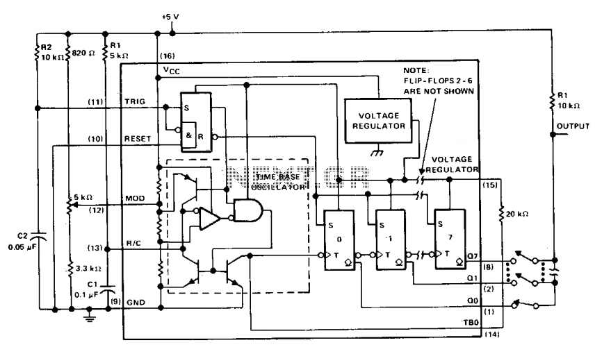
The µA2240 integrated circuit is designed for applications requiring precise timing and frequency generation. It comprises four essential components: a time-base oscillator (TBO), an eight-bit counter, a control flip-flop, and a voltage regulator, each contributing to the overall functionality of the device.
The time-base oscillator generates a clock signal at a frequency determined by the external resistor (R1) and capacitor (C1) values, with a specific time constant calculated as 1R1C1 = 2 kHz. This oscillator's open-collector output is connected to the input of the eight-bit counter, which counts the pulses generated by the TBO. A 20 k ohm pull-up resistor is employed to ensure proper voltage levels at the counter input, facilitating reliable operation.
Upon power-up, the circuit is initialized by a positive trigger pulse detected across capacitor C2. This pulse activates the TBO, initiating the oscillation process and setting all outputs of the counter to a low state. The µA2240 operates in an astable mode, meaning that once triggered, it will continue to run independently until an external reset signal is received. This behavior allows for continuous frequency generation without the need for constant triggering.
The eight-bit counter can synthesize up to 255 distinct frequencies by selectively connecting various counter outputs. This versatility in frequency generation makes the µA2240 suitable for a wide range of applications, including signal generation, timing applications, and digital clock circuits. The integrated voltage regulator ensures stable operation across varying supply voltages, contributing to the device's reliability and performance in electronic designs.The µA2240 consists of four basic circuit elements: (1) a time-base oscillator, (2) an eight-bit counter, (3) a control flip-flop, and (4) a voltage regulator. The basic frequency of the time-base oscillator (TBO) is set by the external time constant determined by the values of R1 and Cl (1R1C1 = 2 kHz).
The open-collector output of the TBO is connected to the regulator output via a 20 k ohm pull-up resistor, and drives the input to the eight-bit counter. At power-up, a positive trigger pulse is detected across C2 which starts the TBO and sets all counter outputs to a low state.
Once the µ2240 is initially triggered, any further trigger inputs are ignored until it is reset. In this astable operation, the µ2240 will free-run from the time it is triggered until it receives an external reset signal. Up to 255 discrete frequencies can be synthesized by connecting different counter outputs. 🔗 External reference
Related Circuits
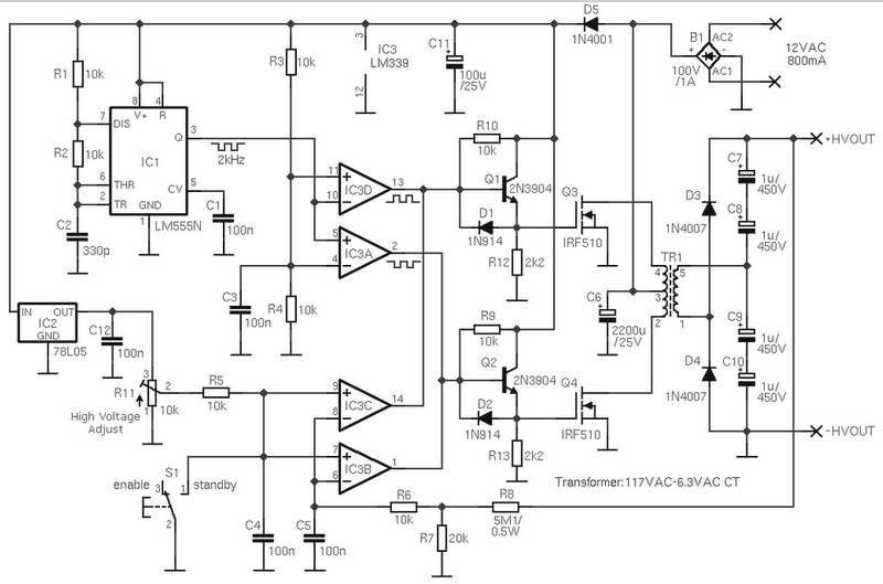
The schematic diagram is derived from the circuit for an Adjustable High Voltage Power Supply, which can output voltages ranging from 0 to 1000V. A suitable source of alternating voltage for the high voltage converter is 12V / 800mA....
The most popular network is MED-NET, which encompasses the entire Mediterranean Sea with its observation points. The accompanying map illustrates these observation points. For more information about this network, which is part of the Italian Geophysical National Institute, the...
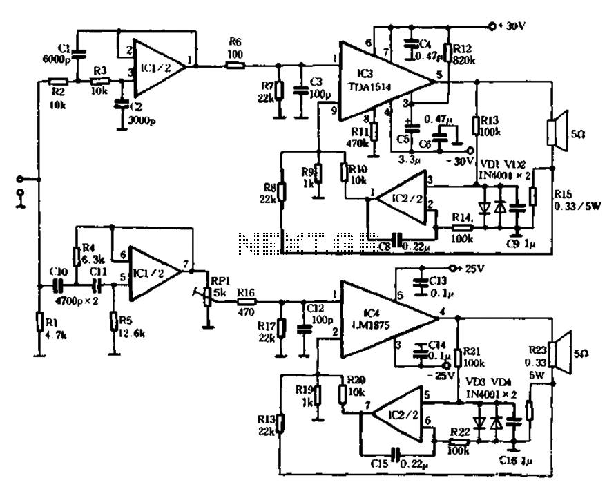
The mechanical and electrical schematic in Figure 5 illustrates a simple circuit comprising several components. The first component is an electronic crossover section utilizing the NE5532 operational amplifier, which is known as the "Emperor of the op-amp." This section...
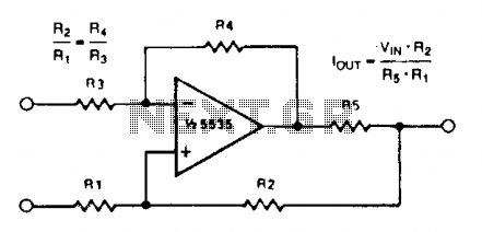
A simple voltage-to-current converter is illustrated. The output current is given by 0t or Vjn/R. For negative currents, a PNP transistor can be employed, and for improved accuracy, a Darlington pair can replace the transistor. With meticulous design, this...
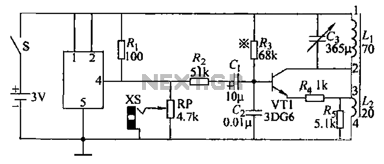
An audio frequency signal generator can output audio signals, 465 kHz spectral amplitude signals, and 52.5 Hz to 16 kHz high-frequency amplitude-modulated signals. The high-frequency oscillator's vibration frequency is determined by the components G and L. A variety of...
This high voltage converter circuit operates from a 30-volt power supply and can output a voltage ranging from 0 to 3 kV in version 1 or from 0 to 10 kV in version 2. The high voltage converter circuit is...
Warning: include(partials/cookie-banner.php): Failed to open stream: Permission denied in /var/www/html/nextgr/view-circuit.php on line 713
Warning: include(): Failed opening 'partials/cookie-banner.php' for inclusion (include_path='.:/usr/share/php') in /var/www/html/nextgr/view-circuit.php on line 713