
PLL systems

More: More specifically, a PLL is a circuit that synchronizes an output signal, generated by an oscillator, with a reference or input signal in both frequency and phase. In the synchronized state, often referred to as the locked state, the phase error between the oscillator's output signal and the reference signal is either zero or very minimal. If a phase error does occur, a control mechanism adjusts the oscillator to maintain a small phase error. In this control system, the phase of the output signal is effectively locked to the phase of the reference signal, which is the reason it is termed a phase-locked loop.
A phase-locked loop consists of several key components: a phase detector, a low-pass filter, and a voltage-controlled oscillator (VCO). The phase detector compares the phase of the input reference signal with that of the VCO output. When a phase difference is detected, the phase detector generates an error signal proportional to the phase difference. This error signal is then filtered by the low-pass filter to remove high-frequency components, producing a smooth control voltage.
The control voltage is fed to the VCO, which adjusts its frequency according to the voltage level. As the VCO output frequency approaches the frequency of the reference signal, the phase difference decreases. Once the PLL achieves a locked state, the output frequency of the VCO remains synchronized with the reference signal, effectively eliminating phase error.
PLLs are widely utilized in various applications, including frequency synthesis, demodulation in communication systems, and clock recovery in digital circuits. Their ability to maintain synchronization under varying conditions makes them essential for reliable operation in electronic systems. The design and optimization of PLL circuits require careful consideration of factors such as loop bandwidth, stability, and response time to ensure effective performance in the intended application.The phase-locked loop (PLL) helps keep parts of our world orderly. If we turn on an analogue television set, a PLL will keep heads at the top on the screen and feet at the bottom. Incolor television another PLL makes sure that green remains green and red remains red even if the politicians claim that the reverse istrue).
A PLL is a circuit which causes a particular circuit to track with another one. More precisely, a PLL is a circuit synchronizing an output signal (generated by the oscillator) with a reference or input signal in frequency as well as inphase. Inthe synchronised - often called locked - state the phase error between the oscillatorr`s output signal and the reference signal is zero, or verysmall.
Ifa phase error builds up, a control mechanism acts on the oscillator in such a way that the phase error is kept small. Insuch a control system the phase of the output signal is actually locked to a phase of the reference signal.
Thisis why it is referred to as a phase-lockedloop. 🔗 External reference
Related Circuits
A phase-locked loop (PLL) is a servo system, or a feedback loop that operates with frequencies and phases. PLLs are known to be quite useful in communication systems, where they can extract small signals from significant noise. This discussion...
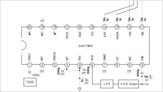
The output frequency can be altered based on the division ratio of the comparison frequency in the 10 kHz unit, with the division ratio set to 1024 in this circuit. Given that the amateur radio bandwidth in Japan is...
The CXA1821M is an integrated circuit designed for compact disc players. This IC includes an Automatic Power Control (APC) circuit along with RF, focus error, and tracking error amplifiers for 3-spot optical pickup output. It also supports voltage-converted optical...
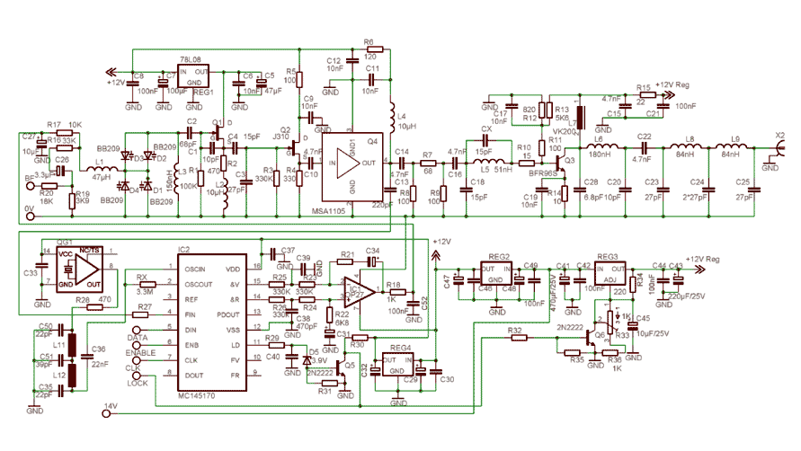
In order to simplify the transmitter design, we've used the new pll circuit from Motorola: the MC145170. This PLL includes the prescaler and a serial standard bus called SPI. We advise to use the P2 version that fixes some...
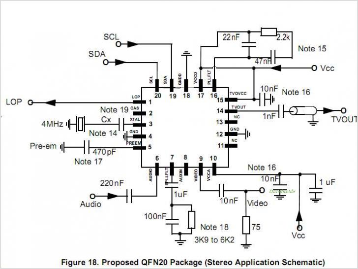
MC44BS374CA: PLL Tuned UHF and VHF Audio Video High Integration Modulator MC44BS374CA The MC44BS374CA Audio and Video Modulator is for use in VCRs, set-top boxes, and similar devices. By Freescale Semiconductor, Inc The MC44BS374CA is a highly integrated audio and...
The FM demodulator circuit, as illustrated in the figure, utilizes a 4046 Phase-Locked Loop (PLL) integrated circuit to convert the intermediate frequency FM input signal into a lower frequency output. The FM demodulator circuit based on the 4046 PLL IC...