
The PLL FM demodulator (4046) circuit
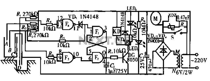
The FM demodulator circuit based on the 4046 PLL IC operates by employing phase-locked loop techniques to achieve demodulation of frequency-modulated signals. The 4046 IC includes a voltage-controlled oscillator (VCO) and a phase comparator, which are integral to the demodulation process.
In this configuration, the FM input signal is fed into the phase comparator, which compares the phase of the incoming signal with the output of the VCO. Any phase difference detected results in an adjustment of the VCO frequency, effectively tracking the frequency variations of the FM signal. This tracking action allows the circuit to convert the frequency variations into corresponding voltage changes, which represent the original audio or data signal.
The output of the VCO is then filtered to remove high-frequency components, resulting in a low-frequency output that is a replica of the original modulating signal. Additional components such as resistors and capacitors may be included in the circuit to set the bandwidth and stability of the PLL, ensuring optimal performance for the specific FM signals being demodulated.
Overall, the 4046 PLL-based FM demodulator circuit is a robust solution for demodulating FM signals, suitable for various applications in communication systems where reliable and accurate signal processing is essential.See as the figure, the FM demodulator circuit consists of 4046 PLL particles, the intermediate FM input signal is demodulated into the low frequency by the circuit.. 🔗 External reference
Related Circuits
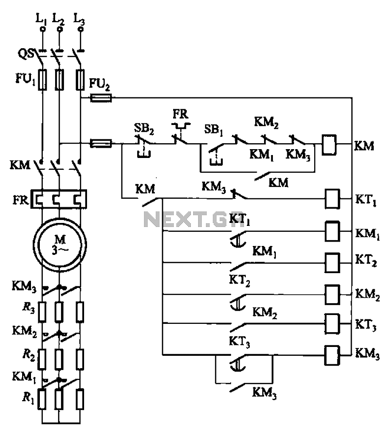
The circuit depicted in Figure 3-159 employs complementary operation three times along with three relay contacts. This is followed by the automatic elimination of the rotor circuit resistance levels, ultimately reducing the rotor winding variable resistor to zero (fully...

The AVANT employs a Switched Mode Power Supply (SMPS), which is centered around a 32 kHz ramp oscillator. This oscillator ceases operation if the overload protection circuit identifies an overload condition. When the oscillator is inactive, the 8-volt standby...

To utilize this facility, the calling subscriber must first dial the standard phone number of the intended recipient. Once the call is connected, the calling party does not hear a ring-back tone. The calling subscriber must then press the...
The circuit contributes 3.2 nV/√Hz of voltage noise and 0.45 pA/√Hz of current noise. To minimize noise from other sources, resistor R3 is configured to 100 ohms, resulting in an additional voltage noise of only 1.3 nV/√Hz. Resistors R1,...
The circuit operates by monitoring the water level in a tank. When the water level falls below a specified point (F), the RS flip-flop (F2) is activated, producing a high Q output that energizes a relay to start the...

Engineer Radu Preda from Romania has developed two energy-saving lighting circuits designed to control the duration that lights are activated, ultimately aiming to reduce electricity expenses. The first circuit utilizes a relay, while the second employs an optoisolator triac...
Warning: include(partials/cookie-banner.php): Failed to open stream: Permission denied in /var/www/html/nextgr/view-circuit.php on line 713
Warning: include(): Failed opening 'partials/cookie-banner.php' for inclusion (include_path='.:/usr/share/php') in /var/www/html/nextgr/view-circuit.php on line 713