
Unity gain line from the MAX4450 4451 a driving circuit diagram
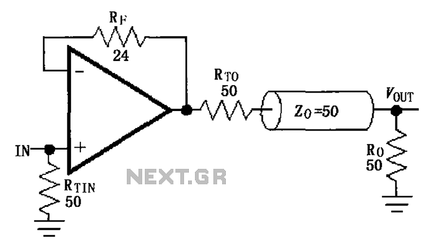
The MAX4450 and MAX4451 are precision operational amplifiers designed for high-speed applications with a unity gain configuration. In this setup, the internal compensation allows for stable operation across a broad frequency range, which is critical for maintaining signal integrity in communication systems.
The inclusion of a 24-ohm resistor in series within the feedback loop serves to set the gain and improve linearity, while the parallel capacitors and inductors are strategically selected to reduce the Q factor. A lower Q value indicates a broader bandwidth and improved transient response, which is essential for high-frequency signal processing.
The choice of a coaxial cable transmission line is significant for minimizing reflections, which can lead to signal degradation. By selecting a terminating impedance of 50 ohms, the system ensures that the output impedance of the amplifier matches the characteristic impedance of the transmission line. This impedance matching is crucial for maximizing power transfer and minimizing signal reflections, which can adversely affect the performance of the circuit.
In summary, the design of the MAX4450/4451 driving circuit incorporates various components and configurations that collectively enhance the communication characteristics of the system, ensuring efficient signal amplification and transmission. As shown by FIG MAX4450/4451 unity gain line in the driving circuit. MAX4450/4451 has internal compensation, a 24 resistor in series in a feedback loop, capacitors, and inducto rs can reduce the Q value of the feedback loop is formed in parallel to improve communication characteristics of the circuit. The output of the signal amplification using coaxial cable transmission line, for the transmission of the reflection minimum, to obtain the maximum power load, select terminating impedance (50 ), the amplifier output impedance and the characteristic impedance of the transmission line is equal to three, i.e., impedance matching.
Related Circuits
A fluorescent tube is connected in an LC resonant circuit consisting of inductor L2 and capacitor C9. The bidirectional breakdown diode VD4 initiates the starting circuit. When AC power is applied, the gate potential of transistor VT2 increases due...

A simple 16-volt switching power supply circuit can be constructed using the provided diagram, which is based on the MAX668 constant-frequency, pulse-width modulating (PWM), current-mode DC-DC controller. This integrated circuit is designed for a wide range of DC-DC conversion...
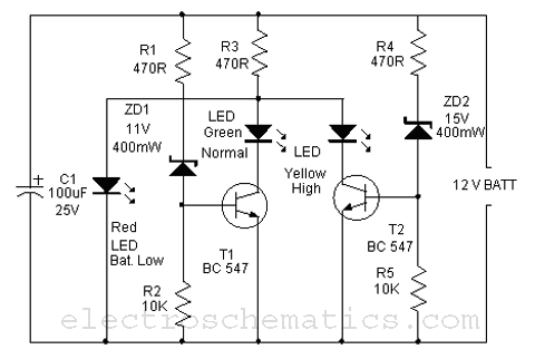
This is a simple battery monitor circuit designed for a quick assessment of a 12-volt lead-acid battery. Continuous monitoring of battery charge is essential to extend its lifespan. The battery monitor circuit typically consists of a voltage divider, an operational...
The following circuit illustrates the RF block diagram of a GPS receiver. This circuit is based on the MAX2742 integrated circuit. Features include a complete GPS receiver functionality. The GPS receiver RF block diagram utilizing the MAX2742 IC encompasses several...
Figure 2-33 (a) illustrates the schematic diagram of a robot approaching an object. When no objects are detected in front of the robot, it moves forward in a straight line. If an object is detected on the left or...
This is a variable power supply controlled by a PIC microcontroller. An LCD display is included in the circuit to show the actual output voltage and current values. A push-button switch is used to adjust the output voltage and...
Warning: include(partials/cookie-banner.php): Failed to open stream: Permission denied in /var/www/html/nextgr/view-circuit.php on line 713
Warning: include(): Failed opening 'partials/cookie-banner.php' for inclusion (include_path='.:/usr/share/php') in /var/www/html/nextgr/view-circuit.php on line 713