
Police siren
The electronic schematic described incorporates a 4060 binary counter at its core, which serves as the master clock for a sequencer project. The design features an internal clock and outputs that can be selected for frequency division, allowing for complex sequencing capabilities. The addition of external clock inputs enhances versatility, enabling the generation of extended sequences suitable for live performances. The use of NAND gates for inversion introduces a musical quality to the output, while the inclusion of summing amplifiers allows for greater control over the signal's characteristics. The design encourages experimentation with component values, promoting a hands-on approach to electronic circuit design. The cardboard PCB methodology presents an innovative and sustainable alternative for prototyping and building electronic projects, making it accessible to a broader audience. The integration of various components, such as the CD4069 and CD4040, showcases the adaptability of CMOS technology in creating unique sound synthesis and processing circuits. The overall project exemplifies the fusion of creativity and engineering, resulting in engaging and functional electronic instruments.This blog shows project documentations of various projects done by members of association of experimental electronics. Some projects are very easy and suitable for beginners, some are only for more advanced solderers. The core parts of this sequencer were assembled during Modular Collective Instrument workshop (given by Kokomys in Mansedanse 2011
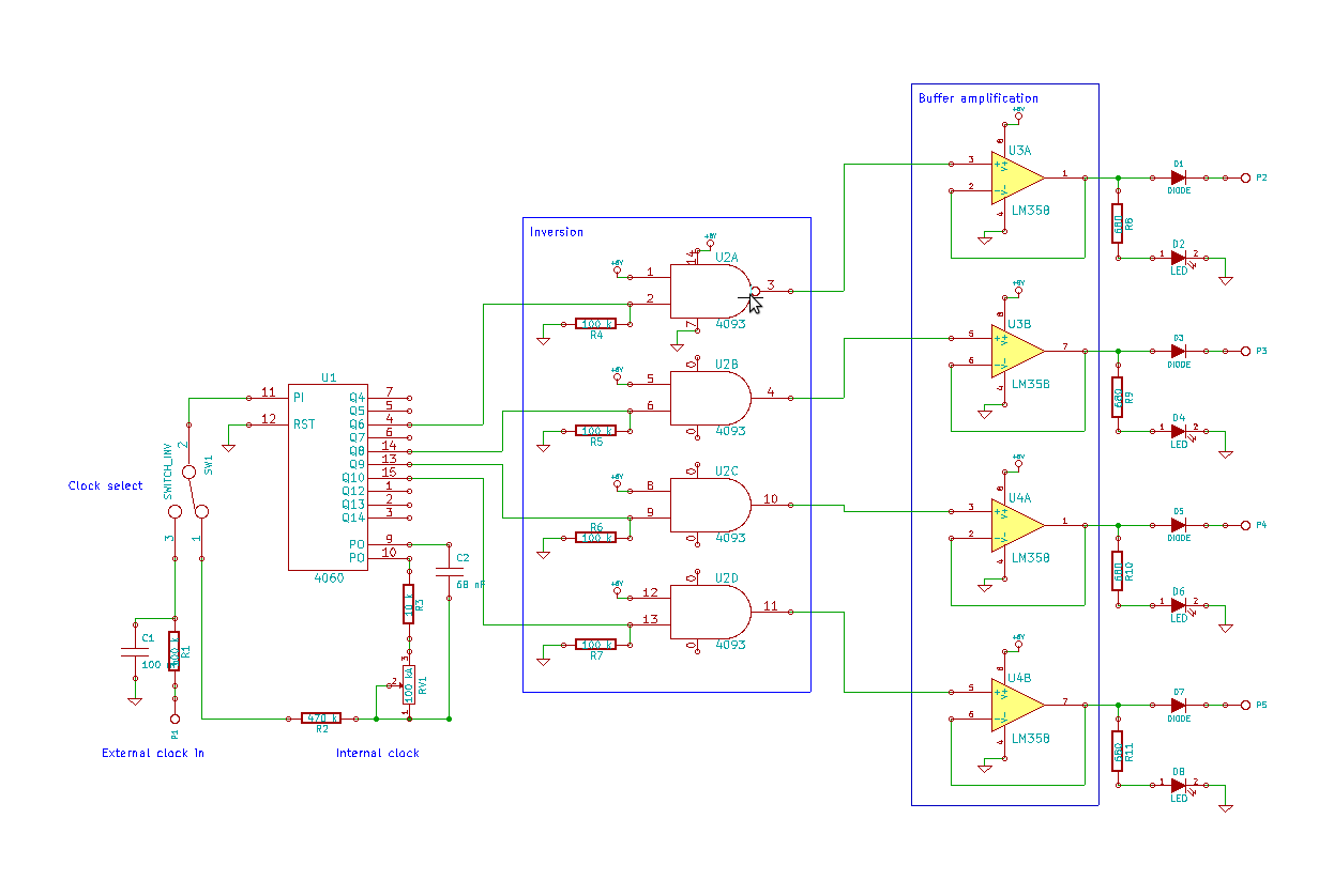
festival ) as the master clock for the Instrument. The core has a simple 4060 binary counter with internal clock, with two outputs with 1/4 frequency ratio and a pot for frequency control. For 101 sequencers project, I expanded the sequencer to have four outputs and external clock signal input, selectable by switch.
When the external clock is in use, 4060 performs frequency division, giving out 1/64, 1/256, 1/512 and 1/1024 of the input signal. This will be used to create longer sequences. With one hundred and one sequencers on the stage, we can afford very long sequences also. Since 4060 is a ripple counter, the circuit also contains an inversion stage, making the different outputs change state in a maybe more musical way.
NAND gates are used for inversion instead of simple inverters simply because 4093 was on hand at the moment. It uses one inverter from cd4069 as a summing amplifier. You can add more channels by repeating the input circuitry (100k pot, 0, 1uF cap, 47k resistor) The 500k pot is gain and will give a nice amount of distortion if/when needed :) You can use a single 4069 chip to build both filters in the previous post and this mixer.
Here are two easy to build filter circuits based on the cd4069 chip. I ve used them in my recent projects and I m quite pleased how they work. These schematics are examples meant to be a starting point and the component values are examples so feel free to experiment with different values. It uses three inverters. So you can build two with a single 4069. R1 and R2 are the cutoff frequency use a 10k-20k stereo pot or two ldrs and leds driven with a cv source (lfo, sequencer etc.
). Cap values are drawn 0, 1uF but I ve built one with 0, 047uF and it worked fine. The 100k pot is resonance, and this filter will oscillate when resonance is turned up. There are two output options drawn in the schematic "out" (wich is more bassy) and "out2". You might want to use a output cap (1uF). This thing uses only one inverter. Try different cap values instead of 0, 01uF ones(maybe from 0, 001 to 0, 068) and they dont all need to be the same. This is also voltage controlled with the npn-transistor you can use a pot to ground, ldr etc. insead if you like. I made this cmos 40106 based noisemaker as a dubsiren or something. It has 1 oscillator and 2 LFOs. I didn t have any plans when i started just a 40106 chip and some components. First i built a simple squarewave osc from 1/6 of the chip ran it through pulsewidht modulator (again 1/6 of 40106) with Lfo (1/6) Then i added second lfo with led and ldr for pitch modulation.
The best part was "starve" pot ->just a 10k pot in series with battery + to ic pin 14. Some really crazy sounds can be made with playing with this pot. Here is a schematic of the oscs and lfos The component values are what i happened to have so try different values for the results you like. Add more buttons, switches etc. for more playability (only 1 button in the schematic for output) for example i did a powercut button (normally closed) with cap in parallel (47 uF) work in progress videos and and a video of the finished piece The idea for making electronic projects on cardboard came from Ciat Lonbardes paper circuits.
I had used veroboard previously. But it was a bit difficult to change more complicated designs to work on veroboard. Also making pcb:s at home seemed complicated with all chemicals, UV-lamps etc. Cardboard may not be the most sturdy material, but it is cheap, always available, environment friendly and it works. I also have a pretty good collection of circuit boards from broken equipment. A lot of components (resistors, caps, transistors etc. ) can be recycled from these. So using cardboard pcb and recycled components you can build electronic projects at home more environment friendly and you don`t need to spend any money on the parts.
(Of course some parts are a bit difficult to find from random broken equipment. ) 1. you can print picture of the pcb you want on paper and then glue it on a piece of cardboard. Or design your own circuit by drawing it. Postcards can easily be used as material. 3. insert the components and solder them according your pcb design. In most cases components reach each other with no jumper wire. But when using recycled components the pin are often cut bit too short so you might need jumper with them. I have been building some noisemakers using cardboard as pcb. It s a nice material for building electronic projects at home because: 1. everybody may not have the needed equipment to make "real" pcb:s 2. every one has a piece of cardboard laying around. 3. It is cheap and easy. This is my latest creation on cardboard pcb. It s wp-20 sound effects synth. It was very nice to do on cardboard because there was enough spce between components in the original pcb design.
I did t use the original noise source with 18v but i built a simple 9v noise generator. I left q1, r1, c3 unconnected to the board. here is the noise circuit. I made a sub oscillator for my wp-20. It is based on cd4040 ripple counter it uses the vco squarewave (before the 100k resistor marked R8 in the original wp20 schematics) as clock input and divides it. Six switches (from 1 octave down to 6 octave down) select the harmonics to vcf-vca. The circuit is quite simple the component values may be tweaked to get better performance. I used components that I happened to have so some different values might work better but these seem to work ok.
(sub osc out is connected to ic 2b pin 6 through a 100k resistor like the vco) here is a picture of the circuit You can do it by soldering wires between the in and out lines (r in to r ou and l in to l out) Most homestereo tape players use rca connectors and you can use them as your outputs. You can also do this without soldering if you have proper wires to do the connections ( few rca wires and Y shaped rca adaptor for output from feedbackloop).
Press rec/play to get it working. Frequency of the oscillator is adjusted by turning the tapedecks rec level knobs. The singnal is quite strong so I do not recommend you to plug this to your most expensive or fragile sound gear. 🔗 External reference
Related Circuits

This circuit is designed for children's entertainment and can be installed on bicycles, battery-powered cars, motorcycles, as well as various models, games, and toys. When switch SW1 is positioned as indicated in the circuit diagram, it generates the typical...

This circuit is designed for children's entertainment and can be installed on bicycles, battery-powered cars, motorcycles, as well as on models and various games and toys. When switch SW1 is positioned as depicted in the circuit diagram, it generates...
This circuit is designed for children's entertainment and is suitable for installation on bicycles, battery-powered cars, motorcycles, as well as in models and other games. When switch SW1 is positioned as indicated in the circuit diagram, it produces the...
This circuit provides a good siren noise suitable for warding off robot-predators! Change the pitch by adjusting R2, and R5. More: all resistors are 5 or 10 percent tolerance, 1/4-watt all capacitors are 10 percent tolerance, rated 35 volts...
This is a police tone circuit for a siren. It is simple and easy to construct. VR1 and VR2 are used to adjust the delay of the siren sound. The design is straightforward and uncomplicated. The police tone siren circuit...
This circuit is designed for children's entertainment and can be installed on bicycles, battery-powered cars, motorcycles, as well as models and various games and toys. When switch SW1 is positioned as indicated in the circuit diagram, it generates the...