
Polyphase energy metering using ic
To construct a circuit for digital readout of three-phase power consumption utilizing the ADE7762 energy metering IC, several key components and considerations must be taken into account. The ADE7762 is designed for high-accuracy energy measurement in polyphase systems, making it suitable for residential applications where monitoring power consumption across multiple phases is necessary.
The circuit will typically consist of the following components:
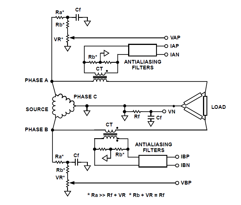
1. **ADE7762 IC**: This chip will serve as the core of the energy metering circuit. It measures voltage and current across the three phases and calculates power consumption, voltage, current, and energy values.
2. **Current Transformers (CTs)**: For each phase, current transformers will be used to sense the current flowing through the wires. These should be selected based on the expected load and should have a suitable turns ratio to provide a measurable output for the ADE7762.
3. **Voltage Divider**: To measure the voltage of each phase, a voltage divider circuit is necessary. This will scale down the high voltage levels to a range that the ADE7762 can handle safely. The resistors in the divider must be chosen carefully to ensure accuracy and safety.
4. **Microcontroller**: A microcontroller may be included to interface with the ADE7762. It will read the digital output from the ADE7762 and can be programmed to display the data on an LCD or send it to a remote monitoring system via wireless communication.
5. **Power Supply**: The circuit will require a stable power supply to operate the ADE7762 and the microcontroller. This can be achieved using a dedicated power supply circuit or by utilizing a switching power supply that can convert the mains voltage to a lower DC voltage.
6. **Filtering Capacitors**: Capacitors should be used in the circuit to filter out noise from the power lines, ensuring that the measurements taken by the ADE7762 are accurate and reliable.
7. **PCB Design**: The layout of the printed circuit board (PCB) is crucial for minimizing interference and ensuring accurate measurements. Careful placement of components and routing of traces will help in achieving optimal performance.
8. **Calibration**: After assembling the circuit, calibration is essential to ensure that the readings from the ADE7762 reflect actual power consumption accurately. This may involve comparing the readings to a known reference and adjusting the circuit as necessary.
By integrating these components and following best practices in circuit design and assembly, a reliable digital readout system for three-phase power consumption can be achieved using the ADE7762. This system will enable homeowners to monitor their energy usage effectively, potentially leading to better energy management and cost savings.how do I build a circuit for digital dead out of 3 phase power consumption in home using any chip like ADE7762 ? I am interested in Polyphase Energy Metering using a.. 🔗 External reference
Related Circuits
This circuit diagram illustrates a simple electronic combination lock utilizing the IC LS7220. The circuit is designed to activate a relay for controlling any device (turning it on and off) when a specific combination of four digits is entered....
Climber A ascends a route while Climber B remains on the ground, tracking Climber A's progress with a laser pointer. The Redpointer device records the exact route taken. In Mode 1, the recorded route is played back in real-time,...

The circuit utilizes a 555 integrated circuit (IC) functioning as an astable multivibrator. When a positive 9 volts is applied to pin 8, the circuit generates sound through a speaker. The connection to pin 8 is routed through a...
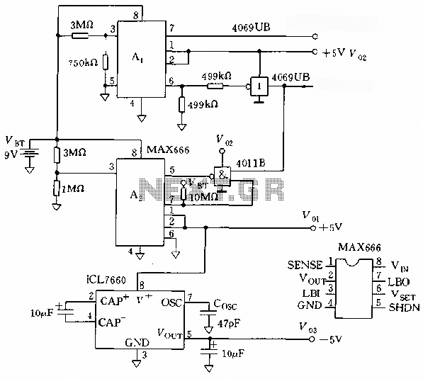
The microprocessor utilizes a linear regulator power circuit that is constructed using two MAX666 devices. The power supply for the CPU and A/D converter is connected to A2, while the RAM and real-time clock receive power from A1. The...
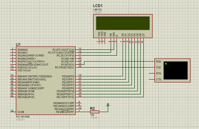
PIC18F4550 communication with a PC using USB HID class, Visual Basic communication. The PIC18F4550 microcontroller is designed to facilitate communication between embedded systems and personal computers through the USB Human Interface Device (HID) class. This microcontroller is equipped with a...
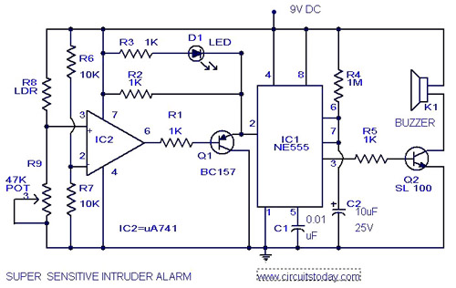
The circuit diagram represents an ultra-sensitive intruder alarm. A shadow from an intruder passing nearby is sufficient to trigger the alarm. The operational amplifier IC2 (uA 741) is configured as a sensitive comparator, with its set point determined by...