
Pong Game Console

The game console operates by utilizing the Arduino microcontroller, which serves as the core processing unit. The TVout library enables the Arduino to generate video signals compatible with standard televisions, allowing the game visuals to be displayed effectively. The project showcases the versatility of the Arduino platform in creating interactive gaming experiences.
The connections between the components are critical for proper functionality. The RCA cable is utilized to transmit the video signal from the Arduino to the TV. The 330-ohm and 1K-ohm resistors are essential for ensuring the correct voltage levels for the video output, preventing damage to the Arduino and the TV. The use of a breadboard facilitates easy prototyping and adjustments to the circuit, allowing for a straightforward assembly process.
The Atari joysticks, which are integral to the gameplay, connect to the Arduino through specific pins that correspond to the joystick's directional controls and button inputs. The selection of pins is based on the joystick's internal wiring, which requires careful identification to ensure accurate control mapping. The first joystick is wired to Arduino pins 2, 3, and 4 for forward movement, backward movement, and button press, respectively. The second joystick is connected to pins 7 and 10 for similar controls, with both joysticks sharing a common ground connection at pin 8.
This project exemplifies the potential for DIY electronics enthusiasts to create their own gaming systems, utilizing readily available components and programming knowledge. Future enhancements could include the integration of additional games or features, such as a game cartridge system to expand the console's functionality. The experience gained from this project highlights the possibilities for innovation within the realm of microcontroller-based gaming systems.I created a simple game console that could play Pong and other games with Atari 2600 joysticks, which the Arduino would read the joystick inputs and output the data to a TV with a TVout library. I created this project just for the fact that I wanted to showcase that anyone can create their own miniature consoles to play, but also I wanted somethin
g fun that the public would enjoy. You`ll need an arduino (m328 preferred), two Atari 2600 joysticks, RCA cable with male connectors, one 330 ohm resistor, one 1K ohm resistor, breadboard, and soldering iron. Give or take, you can also use other hardware to complete this project, like a RS323 socket or a RCA jack for terminal boards.
To describe the steps that this project does, first, after everything is connected, the user will upload the game code to the arduino. Once that`s completed, the data from the game shows up on a TV screen. Finally, two people will be able to maneuver the paddles with the Atari 2600 joysticks to play the game.
Tin both wires with solder. If you lucky, you may be able to insert the video (center) wire directly into the breadboard without any problems. The ground wire (outside) will probably be too bulky to insert directly into the arduino/breadboard, so I spliced it with some wire that`s easier to insert.
Do the same for the video wire if it`s giving you trouble. Now insert both resistors (330 & 1k ohm) into one row on the breadboard (that`s also connected to the RCA video wire). Take the other end of the 330 ohm resistor and insert it into Pin 8 on the Arduino. For the 1K ohm, insert that into Pin 9 on the Arduino. Connect the RCA male connector to a TV and run the TVout library demo for testing. The circuit should look like so (disregard the diodes, they`re not needed): Now we start on the Atari joysticks.
All Atari controllers have 9-pins to connect to the game console, however, for the joystick, there are only 6 holes that actually have pins inside. Looking directly at the holes, we count the pins from 1 to 9 reading right-to-left. Check out my drawing in the circuit diagram section to understand it better. Now, for the specific purpose of playing Pong, we only need 4 pins: Forward (1), Back (2), Button (6), and Ground (8).
For the 2nd joystick, we`ll only need pins 1, 2, & 8 (The Fire button is only used to start the game from title, so that`s why only 1 player will need the button). Rambling aside, I connected those 4 pins with simple wires and attached them to the arduino (Forward` to Pin 2, Back` to Pin 3, & the Fire Button` to Pin 4).
I did the same for the 3 pins on player 2 ²s joystick (Forward` to Pin 7 & Back` to Pin 10). Don`t forget to connect both of the joysticks Pin 8 to ground! When I first decided to take on this challenge, I was extremely excited to begin work on this as soon as I posted it. However, I was not expecting my other classes to bombard me with extra classwork to complete so soon after Thanksgiving holiday.
I had a hard time trying to complete this project and I was worried that I may not finish it on time or not to my expectations. Initially, my main problem was trying to implement the joysticks to the arduino. Due to some internet people not properly writing on the descriptions that the inputs were being read from the inside looking out or that it was actually the paddle controllers, I was scratching my head a lot from being so mind boggled at the pin data for the controllers.
I think the only thing I would do differently for this project would be to somehow implement a sort of game cartridge for the arduino as well, like maybe using SanDisk memory sticks for example. For a Space Invaders game that I showcased today, it almost reached the maximum capacity on the arduino`s memory.
I was also thinking today, after looking at the WU(Shock) project, that maybe if someone loses a round of Pong they`d get shocked. There are millions of possibilities I can explore just because of this minuscule microcontroller that it`s unbelievable.
I`m probably going to buy a Hackvision thanks to this awesome experience. 🔗 External reference
Related Circuits
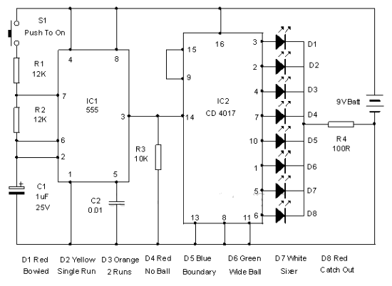
This electronic cricket device is a gift for children. This simple battery-powered circuit can be used to simulate a cricket match with friends. Each LED in the circuit represents various statuses of the cricket match, such as a six,...

The circuit activates a light corresponding to the first button pressed in a "Who's First" game. Three stages are illustrated, but the circuit can be expanded to accommodate any number of buttons and lamps. The described circuit operates as a...
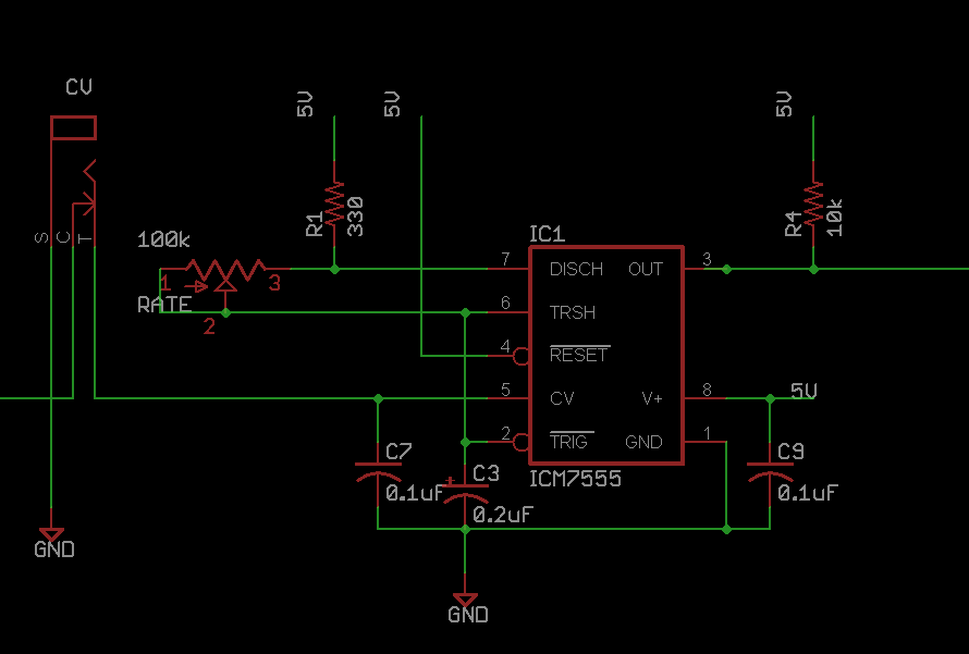
This circuit utilizes two fundamental oscillators that can be assembled as a DIY project, effectively modulating the primary Linear Feedback Shift Register (LFSR) circuit. It also produces interesting audio effects independently. The circuit serves as the main noise generator....
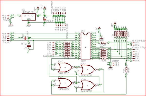
A "Steady Hands Game" was developed to meet the requirement for a cub-scout event. Initially prototyped on a homework board, a more permanent version of the game was created for educational purposes. The final version features a wand (black)...
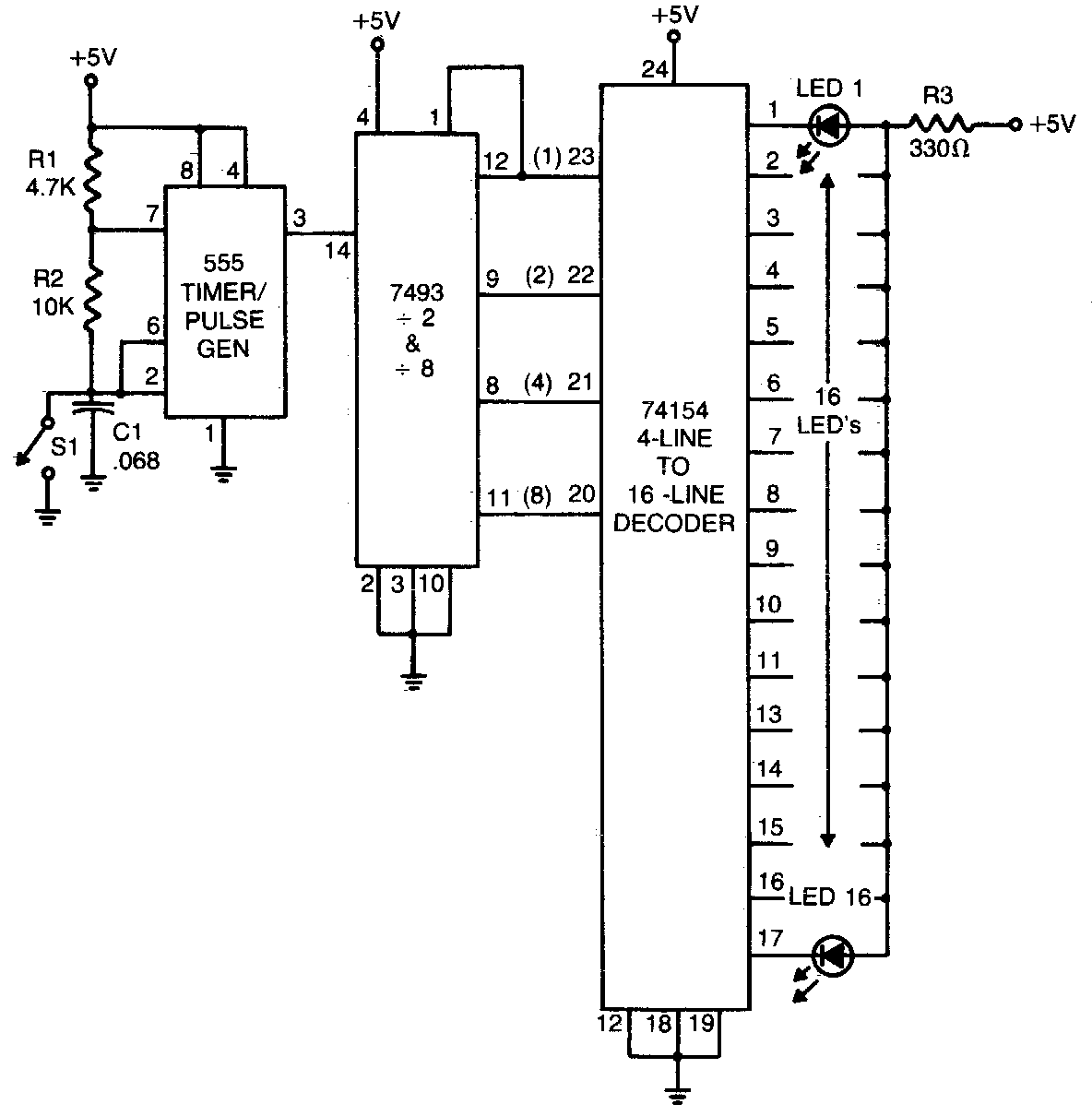
The 555 timer generates a rapid series of pulses when switch SI is open. These pulses are counted in groups of 16 and converted into binary form by the 7493, which is then fed into the 74154, a 1-of-16...

This circuit was designed approximately four months ago and has been developed into a kit for others to use. The circuit in question appears to be a well-thought-out design that has been packaged into a kit format, making it accessible...
Warning: include(partials/cookie-banner.php): Failed to open stream: Permission denied in /var/www/html/nextgr/view-circuit.php on line 713
Warning: include(): Failed opening 'partials/cookie-banner.php' for inclusion (include_path='.:/usr/share/php') in /var/www/html/nextgr/view-circuit.php on line 713