
Game roller or chase circuit
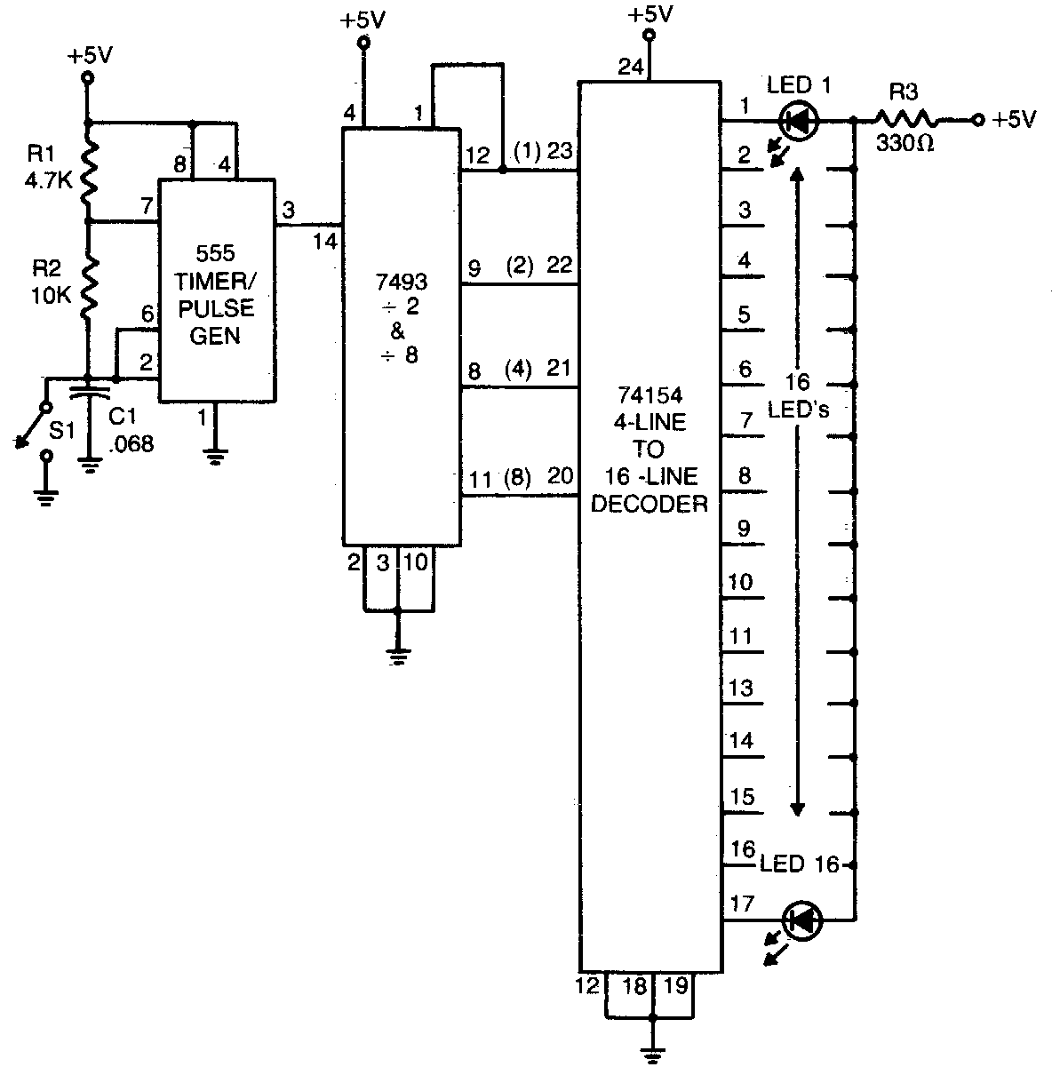
The circuit utilizes a 555 timer configured in astable mode to generate a continuous square wave signal. The frequency of this signal is determined by the resistor and capacitor values connected to the timer. When switch SI is open, the timer produces a series of pulses that are fed into a binary counter, specifically the 7493, which counts the pulses in groups of 16. The output of the 7493 is in binary form and is used to drive the 74154 decoder/demultiplexer.
The 74154 is designed to decode the binary input from the 7493 and activate one of its 16 output lines at a time. Each output line corresponds to a binary count, going low in a sequential manner as the counter increments. This allows for a single LED to be illuminated at any given moment, corresponding to the current count value.
When the switch SI is closed, the circuit effectively halts the pulse generation from the 555 timer. In this state, the 74154 decoder maintains the last active output line, keeping one LED lit while ensuring that the other LEDs remain off. The use of a single current-limiting resistor (R3) for all the LEDs simplifies the design, as only the LED connected to the active output of the decoder will conduct current, preventing the need for multiple resistors and minimizing component count.
This design is efficient for applications requiring visual indicators for counting or timing functions, and the sequential illumination of the LEDs provides a clear visual representation of the binary count. The integration of the 555 timer, 7493 counter, and 74154 decoder/demultiplexer creates a robust and effective circuit for pulse counting and LED indication.The 555 timer produces a rapid series of pulses whenever switch SI is open. These pulses are counted in groups of 16 and converted into binary form by the 7493 and applied to the 74154 (a l-of-16 decoder/demultiplexer) wired so that each of its 16 output lines goes low sequentially and in step with the binary count delivered by the 7493. When the switch is closed, only one LED remains onOnly one current limiting resistor (R3) is used for all the LED""s since only one is on at any one time
🔗 External reference
Related Circuits

This circuit is capable of delivering approximately 200W of power output, produced by Phillips Semiconductor. It utilizes two PHP1BN11QT devices and operates with an input voltage range of 30 to 45 Volts DC. The described circuit is a high-power switching...
A simple method for charging a battery from a higher voltage battery is illustrated in the circuit below on the left. Only one resistor is required to establish the desired charging current, which is determined by dividing the difference...
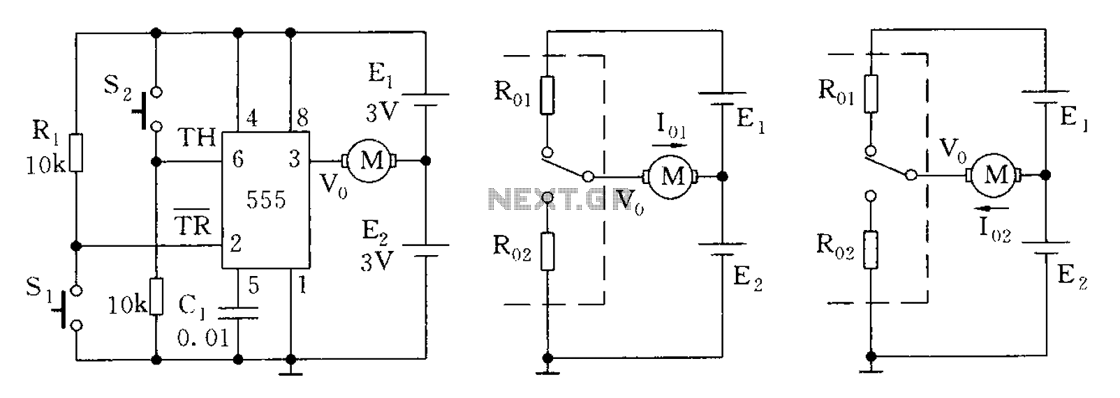
The 555 timer in bistable mode has fewer applications compared to its stable and monostable modes. Bistable mode refers to the circuit configuration based on the R-S (Reset-Set) trigger mode. An example of this is a micro-motor reversing control...
This magic lamp appears to be an ordinary frosted light bulb with a rather unusual characteristic. Whenever a finger touches the base threads and center contact, the lamp magically lights up without wires. It creates a compelling illusion if...

A sensor activates transistor Q1 to turn on the low-frequency 555 oscillator, which generates pulses to control LAMP II. The sensor may respond to variations in light or temperature. Either resistor RA or RB can function as the sensor,...
The bicore is the basis of advanced BEAM. Most intermediate to advanced BEAM robots are built off of the bicore. Uses go all the way from photovores to servo motor drivers to walkers. What it is is basically just...
Warning: include(partials/cookie-banner.php): Failed to open stream: Permission denied in /var/www/html/nextgr/view-circuit.php on line 713
Warning: include(): Failed opening 'partials/cookie-banner.php' for inclusion (include_path='.:/usr/share/php') in /var/www/html/nextgr/view-circuit.php on line 713