
Portable Headphones Amplifier

The circuit described is a headphone amplifier designed to interface with various audio sources such as CD players, tuners, and tape recorders. It is capable of driving headphones with a wide range of impedances, specifically tested with models rated at 32, 100, 245, 300, 600, and 2000 Ohms. The schematic provided focuses on the left audio channel, but it is important to note that components B1 (battery), SW1 (switch), J1 (jack), and C3 (capacitor) are utilized for both channels, ensuring a balanced output.
The resistor R3 plays a critical role in adapting the amplifier's output to the headphone's impedance. For headphones with an impedance of up to 300 Ohms, the value of R3 is appropriately calculated. In instances where headphones of 600 Ohms or higher are connected, it is recommended to increase R3 to 100K Ohms to maintain optimal performance.
The amplifier exhibits a current drain of 35mA per channel when driving 32 Ohm headphones, which decreases with higher impedance loads. This characteristic allows for efficient power management while providing sufficient output voltage. The output voltage capability is rated above 2V peak-to-peak across all tested loads, making it suitable for driving a variety of headphone types effectively.
The sensitivity of the amplifier is rated at 90mV RMS input to achieve the specified 2V peak-to-peak output, indicating that it can respond to relatively low input signals. Furthermore, the frequency response of the amplifier is flat from 30Hz, ensuring that it can reproduce low-frequency audio signals accurately without significant attenuation or distortion.
Overall, this headphone amplifier circuit is designed for versatility and performance, making it an excellent choice for audio enthusiasts seeking a reliable solution for driving headphones across a broad range of impedances.Can be directly connected to CD players, tuners and tape recorders. Tested with several headphone models of different impedance: 32, 100, 245, 300, 600 & 2000 Ohms. Schematic shows left channel only. B1, SW1, J1 & C3 are common to both channels. R3 value was calculated for headphone impedance up to 300 Ohms. Using 600 Ohms loads or higher, change R3 value to 100K. Current drain: 35mA per channel with 32 Ohms impedance headphones. Much less with higher impedance loads Output voltage: Above 2V peak-to-peak on all loads Sensitivity: 90mV RMS input for 2V peak-to-peak output Frequency response: Flat from 30Hz 🔗 External reference
Related Circuits

The circuit is a high-power car audio amplifier schematic. It functions as a car audio amplifier using the PA02 and LH0101 integrated circuits (ICs). Each IC delivers an output power of 30W with an 8-ohm impedance. The part list...
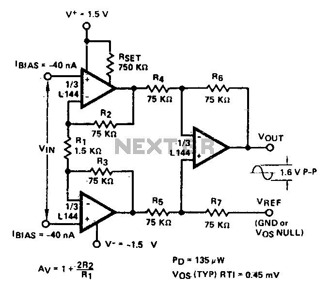
A three-amplifier circuit consumes only 135 µW of power from a ±1 V power supply. With a gain of 101, the instrumentation amplifier is ideal for sensor interface and biomedical preamplifier applications. The first stage provides all of the...
This project is based almost directly on the typical application circuit in the National Semiconductor specification sheet. You can also use the TDA2050 (from SGS-Thompson), which has almost identical performance and (remarkably) the same pinouts! As it turns out,...
The TDA2003 offers enhanced performance while retaining the same pin configuration as the TDA2002. It maintains the advantageous features of the TDA2002, including a minimal number of external components, ease of assembly, and savings in both space and cost....
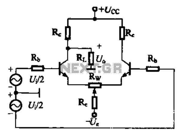
A comparison of four connection methods and features of a differential amplifier circuit is presented. The circuit demonstrates a magnification of a single tube with half the earnings, effectively countering common-mode negative feedback effects. The Common-Mode Rejection Ratio (CMRR)...
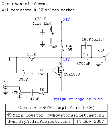
This weblog discusses electronic circuit schematics, PCB design, DIY kits, and electronic project diagrams. It features a simple Class A MOSFET amplifier using the 2SK1058 component. The circuit operates with a 24V supply voltage at high current. It incorporates...