
Differential amplifier circuit four connection methods and features comparison b
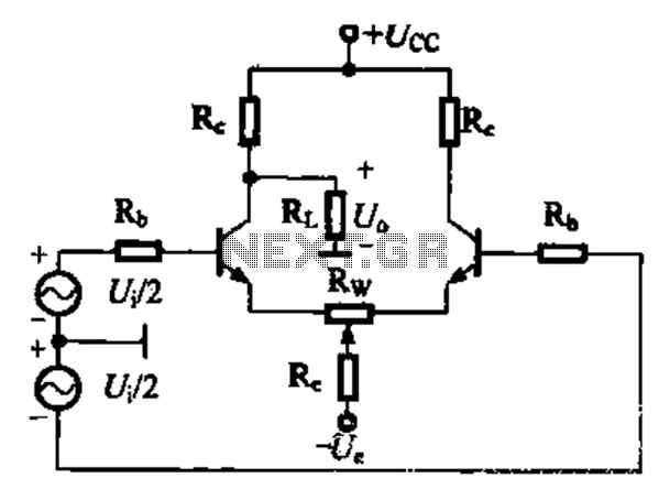
The differential amplifier is a crucial component in analog signal processing, designed to amplify the difference between two input voltages while rejecting any signals that are common to both inputs. This characteristic is essential in applications such as instrumentation, audio processing, and sensor signal conditioning.
The circuit can be configured in several ways, each offering unique advantages and disadvantages. The four primary connection methods typically include:
1. **Direct Coupling**: This method connects the inputs directly to the amplifier without any capacitive coupling. It allows for a wide frequency response but may introduce DC offset issues.
2. **Capacitive Coupling**: In this configuration, capacitors are used to block DC components while allowing AC signals to pass. This is beneficial in applications where DC offset is a concern, but it may limit low-frequency response.
3. **Transformer Coupling**: Utilizing transformers to couple the input signals can provide excellent isolation and help in impedance matching. However, this method may introduce additional complexity and cost.
4. **Feedback Resistor Network**: This method employs a network of resistors to set the gain of the amplifier and improve linearity. It can effectively control the bandwidth and stability of the amplifier but requires careful design to avoid introducing noise.
The differential amplifier's ability to maintain a high Common-Mode Rejection Ratio (CMRR) is critical. CMRR quantifies the amplifier's ability to reject common-mode signals, which are noise or interference present on both inputs. A high CMRR indicates that the amplifier can effectively amplify the desired differential signal while minimizing the effect of unwanted common-mode signals.
In summary, the differential amplifier circuit's design and configuration play a pivotal role in its performance. By selecting the appropriate connection method, engineers can optimize the circuit for specific applications, ensuring high fidelity and reliable operation in various electronic systems.Differential amplifier circuit four connection methods and features comparison b b.0 magnification of a single tube of half earnings due anti-common-mode negative feed-effects, CMRR is still great adapted to the differential signal into a single-ended signal tube-like conditions
Related Circuits
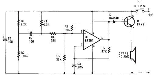
This electronic door buzzer circuit schematic has a straightforward function and is simple to construct. The circuit employs an LF351 operational amplifier along with a few common electronic components. When the S1 push-button is pressed, a positive voltage is...
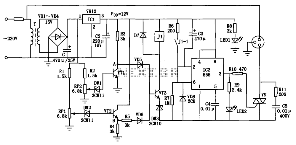
The circuit consists of a DC voltage regulator, a delay circuit, and protection mechanisms for overvoltage and undervoltage. It utilizes the LM7812 integrated voltage regulator to provide a stable 12V output. The protection circuit samples voltage using R2 and...
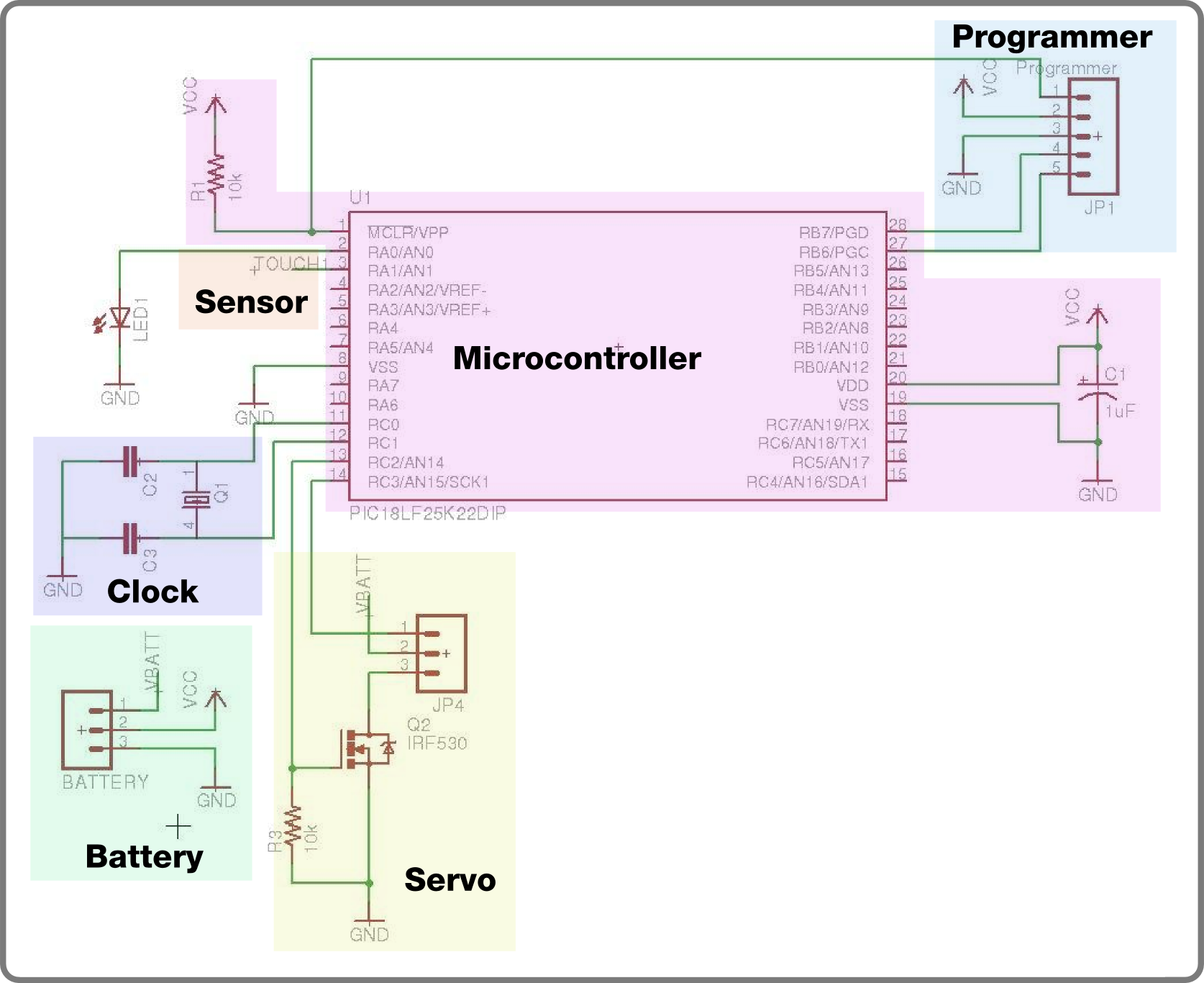
For the second build in the Make It Last Build Series, a robotic plant is being constructed. This week focuses on assembling the control circuit, which will be used in future weeks to animate the plant. The basic circuit...
A 100W RF power amplifier circuit is constructed using two BLY94 transistors. For additional RF amplifier options, refer to the list below. Components include active components. The 100W RF power amplifier circuit utilizing BLY94 transistors is designed to amplify radio...
This audio mixer circuit schematic is designed around four current-controlled amplifiers, all integrated within the SSM2024 IC. The audio mixer circuit utilizes the SSM2024 integrated circuit, which features low-noise, high-performance operational amplifiers suitable for audio applications. The SSM2024 is particularly...
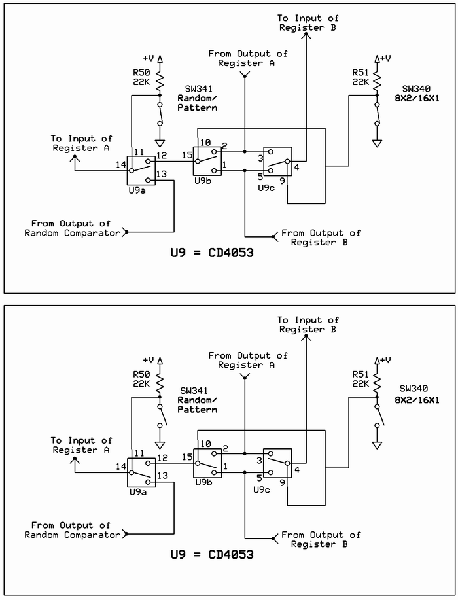
The circuit involves Clock and Load functions, with the Load function being described first. The component U5, a CD4013, is responsible for executing the load function by determining whether the shift register integrated circuits (ICs) operate in parallel or...
Warning: include(partials/cookie-banner.php): Failed to open stream: Permission denied in /var/www/html/nextgr/view-circuit.php on line 713
Warning: include(): Failed opening 'partials/cookie-banner.php' for inclusion (include_path='.:/usr/share/php') in /var/www/html/nextgr/view-circuit.php on line 713