
Portable Microphone Preamplifier

The circuit consists of a two-stage transistor amplifier configuration that enhances the microphone signal before sending it to the home stereo amplifier. The first stage utilizes a PNP transistor, which amplifies the low-level microphone signal. The output of this stage is then fed into an NPN transistor for further amplification. This combination of PNP and NPN transistors ensures low noise and high gain, essential for clear audio reproduction.
The design incorporates a feedback mechanism through resistor R6, which is crucial for stabilizing the amplifier's operating conditions. This feedback loop helps to minimize distortion and maintain linearity across varying input levels. The use of a battery supply not only eliminates potential interference from AC mains but also simplifies the overall power management of the circuit.
For stereo applications, the circuit can be duplicated, allowing for individual control over the left and right audio channels. Each channel can be equipped with its own level control, enhancing the user's ability to balance the audio output as needed. The choice of separate potentiometers instead of a dual-ganged potentiometer offers improved control and flexibility.
The output stage features an adjustable level controlled by potentiometer P1. This potentiometer not only adjusts the output level but also influences the gain of the amplifier stage through resistor R5. By increasing R5's value, the gain is reduced, which is beneficial in preventing clipping and distortion when faced with high input levels. This design allows the circuit to handle a broad range of input signal levels, making it versatile for various microphone types and audio sources.
In summary, this circuit provides a practical solution for integrating a microphone input into home stereo amplifiers, characterized by its low noise, efficient power consumption, and adaptability to different audio sources.This circuit is mainly intended to provide common home stereo amplifiers with a microphone input. The battery supply is a good compromise: in this manner the input circuit is free from mains low frequency hum pick-up and connection to the amplifier is more simple, due to the absence of mains cable and power supply. Using a stereo microphone the ci rcuit must be doubled. In this case, two separate level controls are better than a dual-ganged stereo potentiometer. Low current drawing (about 2mA) ensures a long battery life. The circuit is based on a low noise, high gain two stage PNP and NPN transistor amplifier, using DC negative feedback through R6 to stabilize the working conditions quite precisely. Output level is attenuated by P1 but, at the same time, the stage gain is lowered due to the increased value of R5.
This unusual connection of P1, helps in obtaining a high headroom input, allowing to cope with a wide range of input sources (0. 2 to 200mV RMS for 1V RMS output). 🔗 External reference
Related Circuits
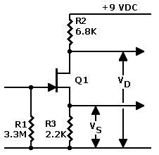
The J201 JFET operates optimally at 10 volts, with a minimum current requirement of 0.5 mA. These specifications are considered ideal, but the actual performance can vary significantly, typically within a range of three to five times. Recent tests...
DCF77 Preamplifier Circuit Diagram A popular project among microcontroller enthusiasts is to build a radio-controlled clock. Small receiver boards are available, equipped with a pre-adjusted ferrite antenna, that receive and demodulate the DCF77 time signal broadcast from Mainflingen in...
Nowadays, audio signal preamplifiers are utilized in numerous electronic devices. There are various types of audio preamp circuits, ranging from simple to complex designs. This document presents an effective design of a compact signal preamplifier circuit, which is ideal...
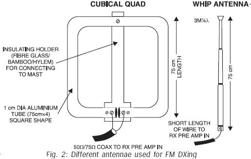
FM transmissions can be received within a range of 40 km. In fringe areas, the signal may be very weak. FM DXing refers to the practice of receiving distant stations (1500 km or more) on the FM band (88-108...
There are neighbors who may disturb you with loud televisions or radios. A solution is available. This jammer emits jamming waves that affect the TVs and radios in the neighborhood, so caution is advised. This device is an enhanced...
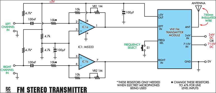
This stereo FM wireless microphone serves as an excellent audio link. Testing revealed a reliable range exceeding 50 meters. It is distinct from previous wireless microphones due to its stereo capability, which delivers unexpectedly high-quality sound. The range was...