
Power Amlifier 40W Class A circuit
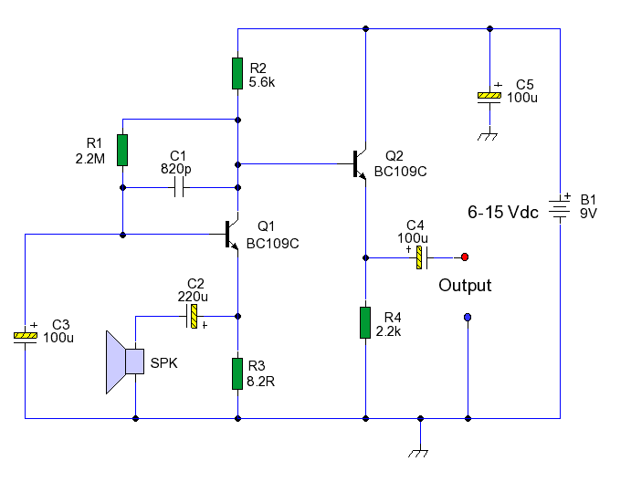
The audio power amplifier described operates in Class A mode, which is known for its linearity and low distortion, making it suitable for high-fidelity audio applications. In this configuration, the amplifier maintains the output transistors in an "always on" state, allowing them to conduct current continuously. This results in a quiescent current that is relatively high, leading to improved signal fidelity but also increased power consumption and heat generation.
The output stage of the amplifier is designed to deliver 40 watts of power into an 8-ohm load, which is a standard impedance for many audio speakers. The choice of Class A operation provides excellent sound quality, as it minimizes crossover distortion, a common issue in other amplifier classes, particularly Class B and Class AB.
To ensure optimal performance, the amplifier circuit includes various components such as biasing networks to set the operating point of the transistors, feedback loops to stabilize gain and improve linearity, and protection circuits to prevent damage from overcurrent or overheating. The power supply must be robust enough to handle the continuous current demand, which is essential for maintaining performance during dynamic audio signals.
Thermal management is also a critical aspect of the design. Heat sinks or other cooling mechanisms are typically incorporated to dissipate the heat generated by the power transistors during operation. This ensures reliability and longevity of the amplifier, especially under prolonged use at high output levels.
Overall, this audio power amplifier is engineered to deliver high-quality sound reproduction with significant power output, making it suitable for various audio applications, including home audio systems and professional sound reinforcement.This is an audio power amplifier, with its final stage giving 40 W/8 ? at Class A. The power transistors, are always ON, allowing a very high current to flow.. 🔗 External reference
Related Circuits
The circuit automatically lights a bulb upon the arrival of a telephone ring and simultaneously mutes the audio from the music system or TV while the telephone handset is off-hook. The lighting of the bulb not only indicates an...
DIY Intercom Circuit Full-duplex intercom circuit schematic, cable on the way to the intercom circuit. The DIY intercom circuit is designed to facilitate two-way communication using a full-duplex system. This allows simultaneous transmission and reception of audio signals, enabling clear...

This display driver circuit illustrates how a Seven Segment Display is driven using the 5-stage Johnson decade counter IC CD4033. The integrated circuit functions as a counter. The CD4033 is a versatile decade counter that can be utilized to drive...
This circuit enables the use of an inexpensive loudspeaker as a microphone. Sound waves that reach the speaker cone create fluctuations in the voice coil. The movement of the voice coil within the speaker's magnetic field generates a small...
This circuit is permanently connected to a mains socket and is designed for trickle charging nickel-cadmium (Ni-Cd) batteries. In the event of a power outage, the lamp automatically turns on. An alarm sounder can be used in place of...
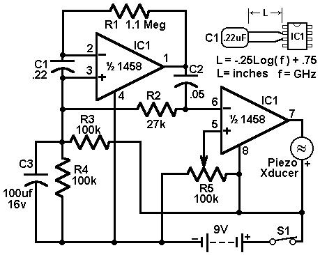
This circuit utilizes a 1458 dual operational amplifier (op-amp) to create a radar detector. Capacitor C1 serves as the sensor for the radar signal. The first op-amp is configured as a current-to-voltage converter, while the second op-amp functions as...