
Economy radar detector circuit
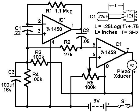
This radar detector circuit employs a dual op-amp configuration, leveraging the 1458 device, which contains two independent, high-gain, frequency-compensated op-amps. The first op-amp is configured to convert the current generated by the radar signal detected by capacitor C1 into a corresponding voltage. This conversion is critical for effectively processing the weak radar signals that may be present in the environment.
The second op-amp acts as a buffer, ensuring that the output voltage from the first stage can drive the piezo transducer without being affected by load variations. This buffering stage is essential for maintaining signal integrity and ensuring that the transducer can produce a clear audible alert when radar signals are detected.
Resistor R5 plays a pivotal role in determining the sensitivity of the radar detection circuit. By setting the switching threshold, R5 allows the circuit to differentiate between actual radar signals and background noise. The ability to adjust this threshold is critical in environments where noise levels can vary significantly. The initial setting should be such that the circuit barely triggers on background noise, allowing for a more reliable detection of radar signals.
Furthermore, the performance of the circuit can be fine-tuned by adjusting the lead lengths of capacitor C1. The specified length of 0.5 to 0.6 inches is optimized for typical road radar systems, as this distance can affect the capacitance and, consequently, the sensitivity and response time of the detector. This adjustment allows for customization based on specific application requirements or environmental conditions.
In summary, this radar detector circuit exemplifies a straightforward yet effective design that utilizes a dual op-amp configuration to detect radar signals. The careful selection of component values and configurations ensures reliable operation, making it suitable for various radar detection applications.This circuit uses a 1458 dual op-amp to form a radar detector. C1 is the detector of the radar signal. The first op-amp forms a current-to-voltage converter and the second op-amp buffers the output to drive the piezo transducer. R5 sets the switching threshold of the second op-amp; normally it is adjusted so that the circuit barely triggers on bac
kground noise, then it`s backed off a bit. The response of the circuit may be tuned by adjusting the length of the leads on C1. For typical road-radar systems, the input capacitor`s leads should be about 0. 5 to 0. 6 inches long. 🔗 External reference
Related Circuits
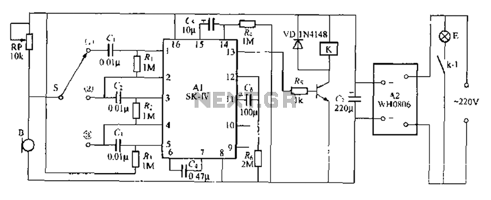
This circuit is a robust light control delay switch with strong anti-interference capabilities. It requires a specific sequence of claps to activate the lamp, which will illuminate for a predetermined duration before automatically turning off. The circuit design is...
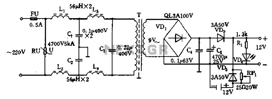
12V DC power supply circuit. A typical 12V DC power supply circuit includes a transformer that converts mains voltage to the required 12V AC output. It features a full-wave rectifier and a capacitor filter. The circuit typically incorporates a...
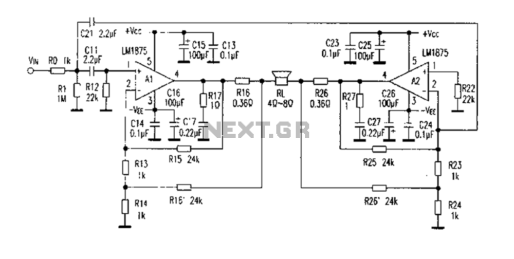
The DC current negative feedback BTL circuit illustrated in Figure 2 eliminates the standard BTL circuit capacitors C12 and C22, which affects the DC characteristics of the circuit. Resistors R16 and R26 function as sampling resistors, while R15, R16,...

In a panic situation during the night when an intruder attempts to break into a house, this alarm system will assist by emitting a loud police siren to deter the intruder. The alarm system is designed to enhance home security...
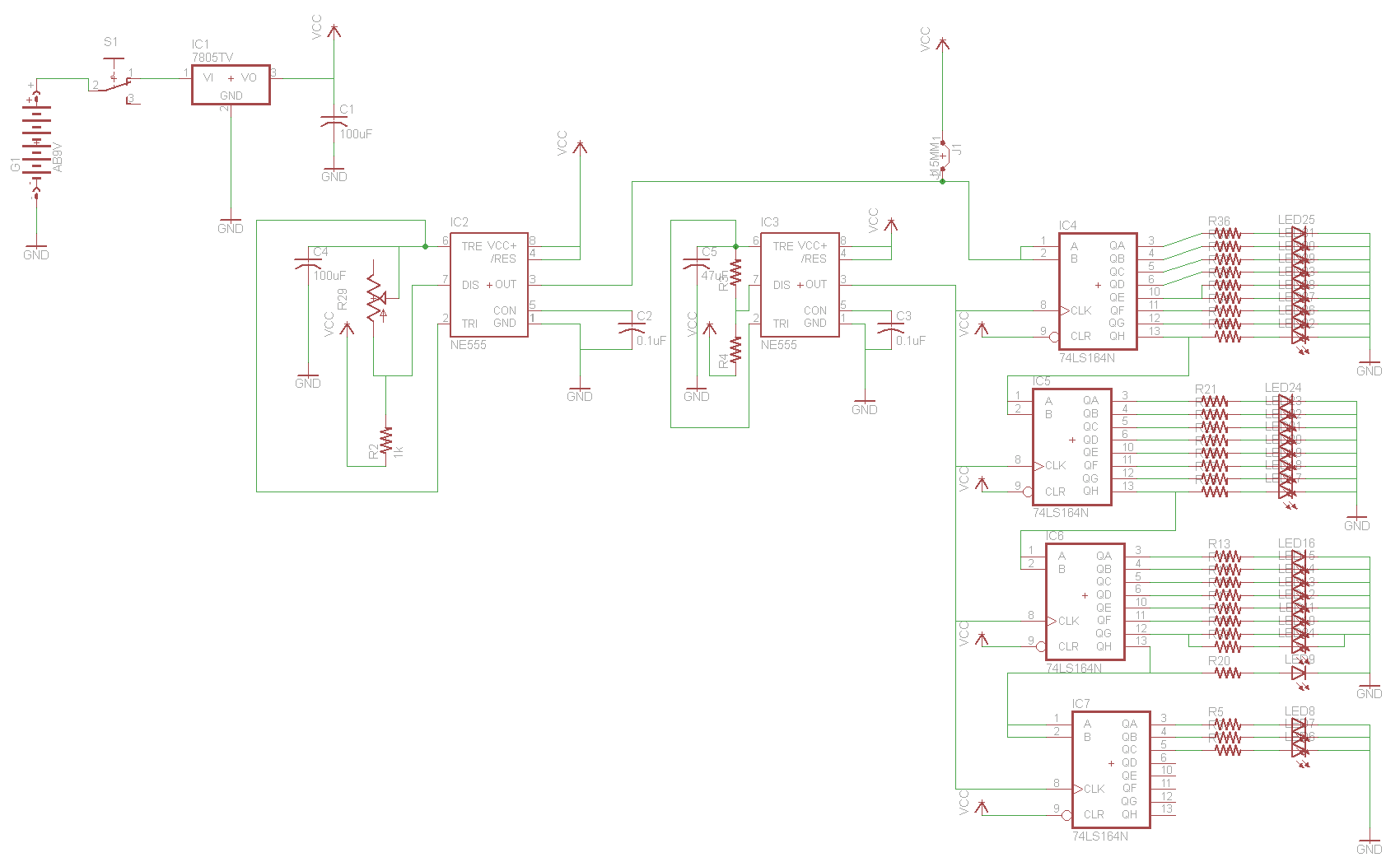
For the two-layer board schematic, six core integrated circuits (ICs) will be utilized: four 74LS164 shift registers and two 555 timers. The schematic will be constructed using the Eagle Layout Editor, as all required components are available in its...
Here is the schematic diagram for a 20 Watt driver. I developed this circuit in 1985, and used it to build a lamp that found much use both as camping light and as emergency light during the then-frequent power...
Warning: include(partials/cookie-banner.php): Failed to open stream: Permission denied in /var/www/html/nextgr/view-circuit.php on line 713
Warning: include(): Failed opening 'partials/cookie-banner.php' for inclusion (include_path='.:/usr/share/php') in /var/www/html/nextgr/view-circuit.php on line 713