
Speaker Mic Circuit
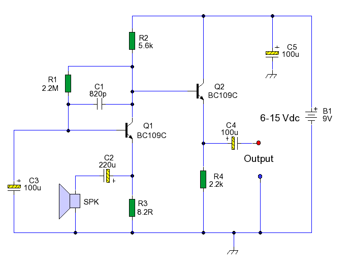
This circuit design leverages the properties of a loudspeaker to function as a microphone by converting acoustic energy into electrical signals. The initial stage employs a common base transistor configuration, which is advantageous in terms of impedance matching. This configuration allows the low impedance of the speaker to be effectively coupled to the amplifier, providing necessary voltage gain for the signal.
The second stage, implemented as an emitter follower, is crucial for maintaining a low output impedance, which is beneficial for driving long cables without significant signal loss or degradation. The direct coupling between stages ensures that the audio signal is transmitted with minimal distortion. The inclusion of capacitor C1 plays a vital role in filtering out high-frequency noise, which is particularly important when the circuit is used in environments with potential RF interference.
Biasing the amplifier to approximately half the supply voltage is a strategic choice that maximizes the dynamic range of the output signal, allowing for greater amplitude swings while minimizing distortion levels. The calculated THD of 1.5% indicates that the circuit can provide a reasonably clean audio signal, suitable for applications where high fidelity is not the primary concern.
The flexibility of using speaker cones with varying diameters and impedances allows for a range of applications, making this circuit a versatile solution for converting sound into electrical signals. Adjusting the 8.2-ohm resistor to match the impedance of the specific loudspeaker used ensures optimal performance, enhancing the overall effectiveness of the circuit. This design provides a cost-effective alternative for audio input applications where traditional microphones may not be feasible.This circuits allows you to use a cheap loudspeaker as a microphone. Sound waves reaching the speaker cone cause fluctuations in the voice coil. The voice coil moving in the speakers magnetic field will produce a small electrical signal. The circuit is designed to be used with an operating voltage between 6 and 12 volts dc. The first transistor o perates in common base mode. This has the advantage of matching the low input impedance of the speaker to the common base stage, and secondly has a high voltage gain. The second stage is direct coupled and operates in emitter follower. Voltage gain is slightly less than unity, but output impedance is low, and will drive long cables. As speakers do not give respond well (as a microphone) to high frequency gain is rolled off by C1, the frequency plot against gain (more commonly known as Bode Plot is shown above).
This roll-off also helps with RF noise immunity when driving long cables. As the amplifier is biased to almost half supply allowing for maximum amplitude swings, its distortion is low, a fourier series to the 16th harmonic (fundamental 1kHz) calculated THD at just over 1. 5%, see above. Speech quality is not as good compared to an ordinary or ECM microphone, but quite acceptable results can be obtained.
Speaker cones with diameters of 1 inch to 3 inches may be used. Speaker impedance may be 4 ohm to 64 ohm. The 8. 2 ohm resistor value may be changed to match the actual speakers own impedance. 🔗 External reference
Related Circuits
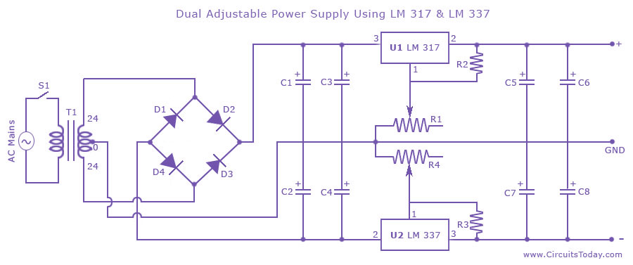
Dual adjustable power supply circuit with a diagram using IC LM317 and LM337. This variable power supply circuit has a range of 1.2 volts to 30 volts. The dual adjustable power supply circuit utilizes the LM317 and LM337 voltage regulators...
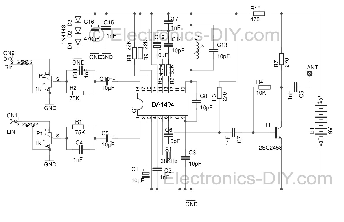
This Stereo FM Transmitter with BA1404 enables the creation of a mini stereo FM station, allowing for wireless audio broadcasting throughout a home. It provides a straightforward method for establishing an audio link without the need for complex wiring....
The color of the LED makes a significant difference. The type and size of the LED, such as 3mm or 5mm, and the power source are crucial factors to consider. More information is required for accurate calculations. A basic...
Even if the circuit is simple, it complies with all conditions regarding distortion and frequency response. The input resistance is 250K ohms, and it can drive loads ranging from 100 ohms to 2K ohms. The described circuit is a fundamental...
The working principle involves two pairs of photoelectric detection devices installed in the access channel. One side features light source A (transmitter) and photoresistor LDR1 (receiver) at the entrance of the channel, while the other side contains light source...
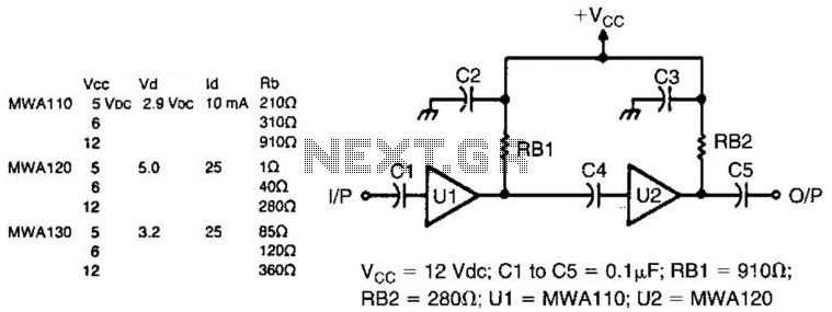
Motorola MWA 110, 120, or 130 are wideband amplifier ICs. This wideband preamp circuit can be used in many applications. Keep the leads short when constructing the circuitry. PC board layout (shading represents copper) and parts layout. X is...
Warning: include(partials/cookie-banner.php): Failed to open stream: Permission denied in /var/www/html/nextgr/view-circuit.php on line 713
Warning: include(): Failed opening 'partials/cookie-banner.php' for inclusion (include_path='.:/usr/share/php') in /var/www/html/nextgr/view-circuit.php on line 713