
Inductive radio alarm circuit
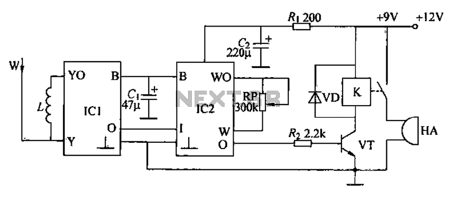
The inductive burglar alarm circuit is designed to provide an effective security solution by utilizing microwave radar technology to detect movement within its operational range. The circuit's functionality relies on the interaction between various components that work in unison to detect disturbances in the electromagnetic field caused by the presence of a person.
The radar detection module (IC1) emits microwave signals and monitors the surrounding environment for any changes. When the area is clear, the output remains low, preventing any alarm activation. The antenna plays a crucial role in transmitting and receiving these microwave signals, ensuring that even slight movements can be detected.
Once movement is detected, the echo signal from IC1 is processed through low-pass filters to eliminate noise and enhance the signal quality. The processed signal is then fed into the signal processing module (IC2), where it undergoes further amplification and delay processing. These steps are essential for ensuring that the alarm system does not trigger from minor disturbances or false positives, providing a reliable response only to significant movements.
The alarm circuit is strategically designed to activate a loud alarm (HA) when the relay (K) is triggered by the output from IC2. The use of a crystal tube (VT) and drop-tubes (VD) helps to manage the current flow and ensure that the alarm operates effectively. The inclusion of a potentiometer (RP) allows for fine-tuning of the circuit's sensitivity, enabling customization based on the specific requirements of the installation environment.
Overall, this inductive burglar alarm circuit exemplifies an advanced approach to security systems, combining radio wave technology with electronic circuit design to create a responsive and reliable alarm mechanism. Circuit inductive burglar alarm circuit from the radio scanning detection circuit, a signal processing circuit and alarm circuit, as shown in Figure 13-43. Radar detected by th e radar detection circuit module block (containing microwave emission, low-pass filtering, gating amplification circuit) IC1, W and antenna inductor L components. Identifying amplified by a signal processing circuit module block IC2 (includes regulator, amplified strobe, soft start, comparing amplification, delay isoelectric driving road), a capacitor Ci, Cz, resistor R.
And potentiometer RP. Alarm circuit by the resistor Rz, crystal tube VT, two drop-tube VD, relay K and alarm HA, microwave oscillator signal (about 1000MHz) (2) Alarm principle IC1 internal oscillation circuit generated by the antenna to the surrounding space W emit high-frequency electromagnetic waves. Scanning radar detection zone within no moving objects, IC2 control output terminal (terminal 0) output low, VT is in ending state.
K in a released state. HA is not sound. When someone moves within the effective range of the radio control scanning detection circuit, the magnetic field space will change. W antenna will detect human body after moving away IC1 points echo signal low-pass processing, the signal output terminal of Ic1 (O side) ultra-low frequency output signal, which is by the IC2 further amplification and strobe delayed drive processing, high output from the control output power peace, so that VT conduction, the relay pull-K, HA powered loud alarm sound.
Related Circuits

The schematic for this project is not overly complex; however, it is crucial to understand the circuit board and its operation due to the high voltages generated. Below is a rough draft schematic of the camera used for this...
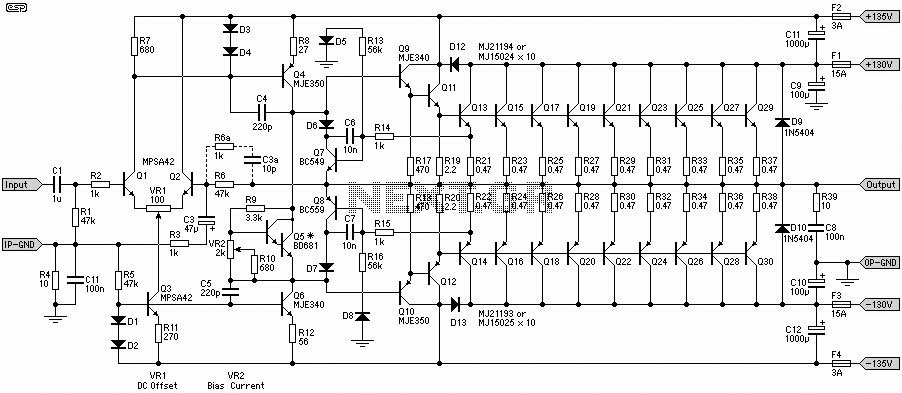
This 1500W Power Amplifier Circuit Diagram contains two images of the circuit. For more complete information, refer to the main post titled "1500 Watt Power Amplifier." It includes a list of component parts for the 1500W Power Amplifier Circuit...
The minimum voltage required for this circuit is 8 volts, while the maximum voltage is 28 volts. It can be used to amplify audio signals in electronic devices such as radios, DVDs, MP4 players, and MP5 players. The circuit...
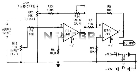
This simple general-purpose driver for an analog/digital converter uses two 741 IC devices with adjustable gain and offset. Other op-amps might be substituted, but some circuit adjustments might be needed. The circuit consists of two operational amplifiers (op-amps) from the...
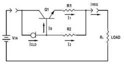
This application datasheet article includes sections that discuss the practical current booster circuit technique, which involves a conventional circuit using a Constant Current Load (CLD) and a current boosting circuit technique. It covers the analysis of the booster circuit...
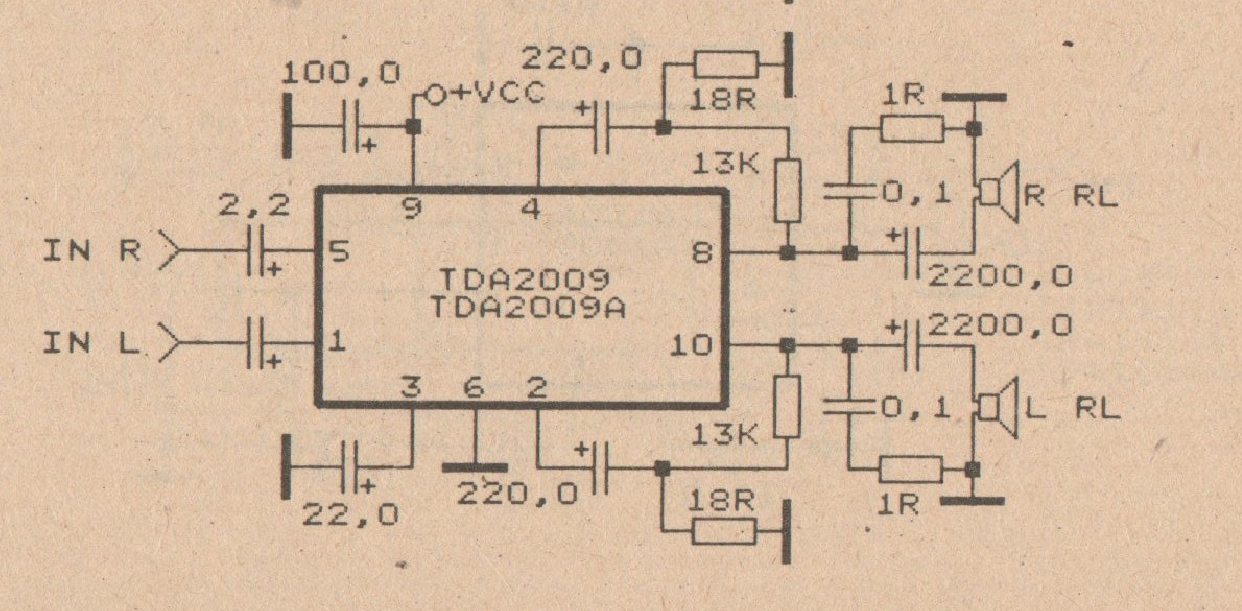
The TDA integrated circuit series is highly regarded and widely utilized in amplifier designs and projects. TDA audio amplifier circuits are primarily produced by Philips and SGS-THOMSON. The most commonly used ICs include the TDA2030 and TDA2003 for small...