
power amplifier speaker protection

The phenomenon described is commonly referred to as "turn-on thump," which is a transient noise generated during the power-up sequence of audio amplifiers. This noise is primarily caused by the rapid charging of coupling capacitors or the sudden application of power to the amplifier's output stage, leading to an immediate surge of current that can drive the speaker cone to its limits.
In direct-coupled amplifiers, where there are no capacitive coupling elements between the output stage and the speaker, the risk of speaker damage is heightened. The absence of capacitors means that any DC offset present at the output can directly affect the speaker, potentially leading to overheating or physical damage if the output stage is not properly controlled during power-up.
To mitigate this issue, several design strategies can be employed. Implementing a soft-start circuit can help in gradually ramping up the power supply to the amplifier, thus reducing the initial surge current. Additionally, incorporating a relay-based speaker protection circuit can disconnect the speaker during the initial power-up phase and reconnect it only after the amplifier has stabilized. This not only protects the speaker from damaging transients but also enhances overall system reliability.
Furthermore, using a delay circuit that monitors the amplifier's output can ensure that the speaker is only connected once the output is stable and free from DC offsets. This can be achieved through a combination of time-delay relays and sensing circuits that detect the presence of DC voltage at the output.
In conclusion, careful consideration of the power-up sequence and the implementation of protective measures can significantly reduce the risk of speaker damage due to turn-on thump in power amplifier designs.While switching a power amplifier on, a loud thump sound is heard to sudden heavy discharge current through the speaker at the time of power on. This current may damage the speaker, especially in case of direct coupled amplifier. 🔗 External reference
Related Circuits
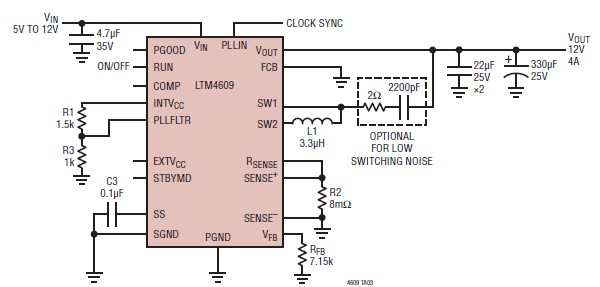
A very simple, high-efficiency switching mode buck-boost power supply circuit can be designed using the LTM4609 switching regulator IC. This circuit will provide a fixed output voltage of 12 volts. As illustrated in the schematic, the switching power supply...
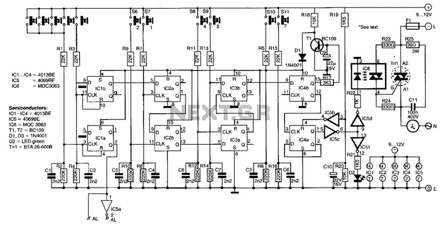
This switch utilizes four CD4013BE dual flip-flops, an inverter, and an optoisolator to control a triac, allowing it to switch a 25-A AC load current. A standard 4x3 telephone keypad is employed for entering a 6-digit code. In the...
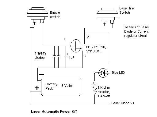
Here is the automatic laser power-off circuit schematic. This circuit features a visible power indication. In this case, the ground is connected on one side. The automatic laser power-off circuit is designed to enhance safety and efficiency in laser applications...
An active amplified transformer isolated signal splitter that enables a hum-free connection of one guitar to multiple amplifiers, while also providing a direct output. This includes a discussion on using audio transformers for equipment interconnections and mentions line-level transformers...
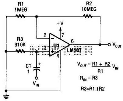
A general-purpose noninverting AC amplifier for audio and other low-frequency applications is presented. Design equations are included in the figure. Almost any general-purpose operational amplifier can be utilized for U1. The circuit configuration features a noninverting amplifier topology, which is widely...
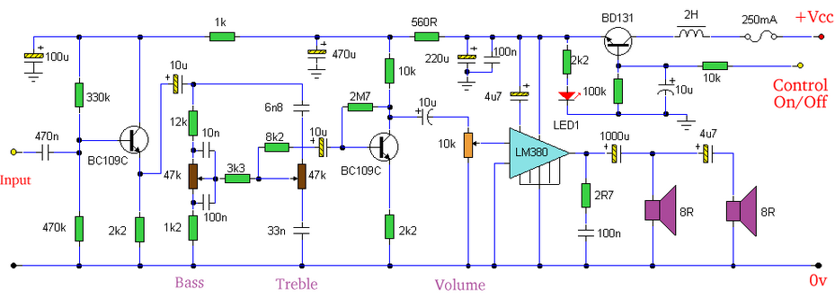
Built around an LM380, this amplifier includes tone controls and electronic soft switching. The soft switching circuitry ensures power is balanced. The LM380 is a power audio amplifier capable of delivering up to 14 watts of output power. It is...