
Noninverting Ac Amplifier Circuit

The circuit configuration features a noninverting amplifier topology, which is widely used for audio signal amplification due to its high input impedance and low output impedance. This configuration allows for minimal loading on the preceding stage while effectively driving the subsequent load.
The operational amplifier (U1) serves as the core component of the circuit, with its noninverting input connected to the audio signal source. The feedback network, typically composed of resistors R1 and R2, determines the gain of the amplifier. The gain (Av) can be calculated using the formula Av = 1 + (R2/R1), where R1 is the resistor connected from the output to the inverting input, and R2 is the resistor connected from the inverting input to ground. This gain configuration allows for precise control over the amplification level.
Power supply connections to the operational amplifier should be made according to the specifications of the chosen op-amp, ensuring that the voltage levels are appropriate for the desired performance. Bypass capacitors may be included between the power supply pins and ground to filter out any noise and stabilize the voltage supply.
Input and output coupling capacitors may also be employed to block any DC components of the audio signal, allowing only the AC signals to pass through. The values of these capacitors should be selected based on the desired frequency response of the amplifier, ensuring that the low-frequency cutoff is below the lowest frequency of interest in the audio range.
Overall, this noninverting amplifier design is versatile and can be adapted for various low-frequency applications beyond audio, making it a fundamental building block in electronic circuit design. A general-purpose noninverting ac amplifier for audio of other low-frequency applications is shown. Design equations are in the figure. Almost any general-purpose op amp can be used for U1.
Related Circuits
The goals were achieved by utilizing a discrete-components operational amplifier (op-amp) driving a complementary common-emitter output stage configured for Class B operation. In this configuration, for small output currents, the output transistors remain off, allowing the op-amp to supply...
The circuit on this page is for a simple light detector circuit board that has 8 detectors that can be used with visible or infrared light systems. The detectors use LM339 voltage comparators as the active element. Phototransistors or...
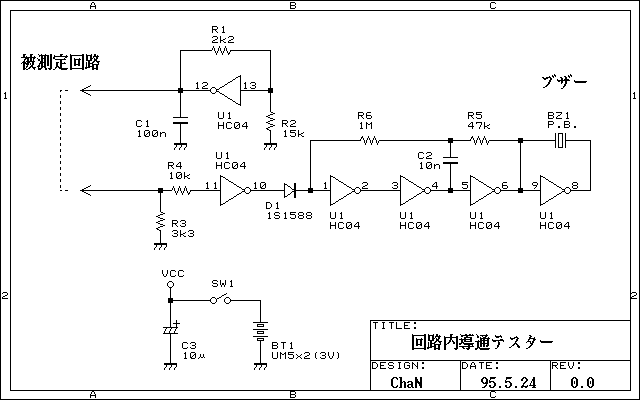
Continuity tester to check continuity in the circuit (Insakittochekka) is. The continuity check over the circuit board wiring that can be checked at a lower voltage semiconductors do not conduct contained in the circuit, you can just check the...
The following circuit illustrates a Video and DVD Modulator in a VHF/UHF electronic diagram. Features include an oscillator that utilizes a transistor for high-frequency operation. The video and DVD modulator circuit serves to convert video signals into a format suitable...
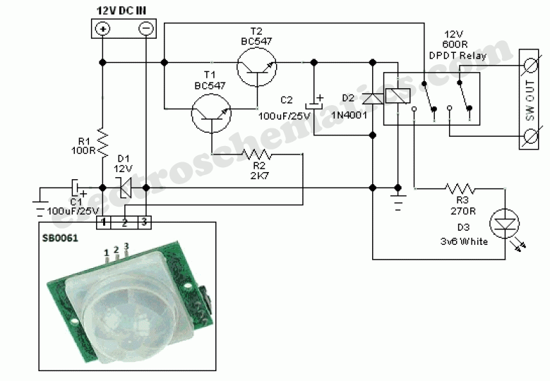
This circuit represents a general-purpose white LED security light equipped with a Passive Infrared (PIR) motion sensing mechanism. The core component of the circuit is the PIR sensor module SB0061, which is a pyroelectric sensor designed for human body...
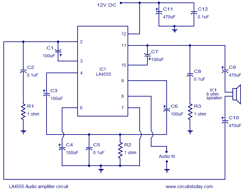
The LA4550 audio amplifier operates in a BTL (Bridge-Tied Load) configuration. This amplifier is capable of delivering 4W into an 8-ohm load when powered by a 12V power supply. The LA4550 is designed for audio amplification applications, particularly in situations...