
automatic laser poweroff circuit
The automatic laser power-off circuit is designed to enhance safety and efficiency in laser applications by ensuring that the laser system can be deactivated automatically under certain conditions. The circuit typically includes a power supply, control logic, and a visual indicator, such as an LED, to signal the operational status of the laser.
The schematic includes a power source connected to a control unit that monitors specific parameters, such as temperature or beam alignment. When the system detects an anomaly, the control unit sends a signal to a relay or transistor that interrupts the power supply to the laser, effectively shutting it down.
The visible power indication is provided by an LED that illuminates when the circuit is active, indicating that the laser is powered on and operational. Conversely, when the laser is turned off, the LED will extinguish, providing a clear visual cue that the system is in a safe state.
Ground connections are critical in this circuit to ensure stability and prevent noise interference. The schematic should clearly mark the ground reference points, which are essential for proper circuit operation. The design may also include additional components such as resistors and capacitors for filtering and stability, as well as protection diodes to safeguard against voltage spikes.
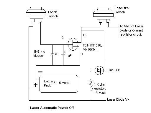
In summary, this automatic laser power-off circuit schematic is an essential tool for maintaining safety in laser operations, providing both automatic shutdown capabilities and clear visual indicators for user awareness.Here`s the Automatic Laser poweroff circuit schematic. This circuit provides a visible power indication. In this case, Ground is waiting on one side.. 🔗 External reference
Related Circuits
This is a straightforward liquid detector that utilizes a relay to activate an evacuation valve. It can be employed for water or any conductive liquid. The liquid detector circuit operates by leveraging the conductivity of liquids to trigger a relay....

This preamplifier features a built-in regeneration control that enhances gain selectivity. CI represents a single or multi-gang AM broadcast-band tuning capacitor, while LI is a ferrite loop antenna tapped at approximately 15 to 25% of the total turns. This...
Hello everyone, I am not well-versed in electronics, so I would appreciate it if someone could create a diagram for me. I would like to modify a circuit so that it can dial a number using speed dial and...
There is an advantage in using continuously active PWM signals. The main reason is that the asynchronous frequencies of the PWM core and microcore can sometimes result in a shortened PWM pulse. The servo recognizes this as a command...
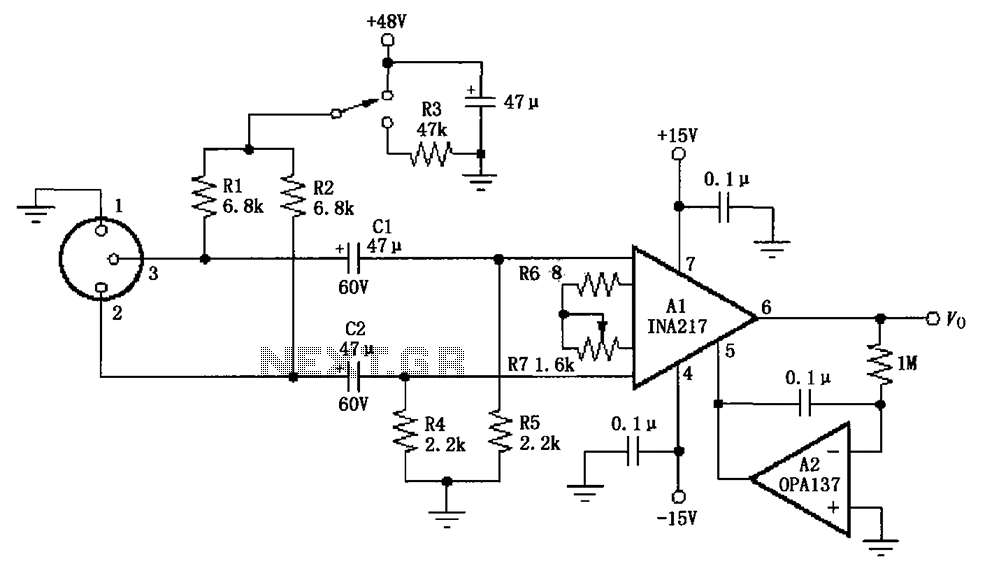
The circuit depicted in the figure consists of an INA217 professional miniature microphone preamplifier. A switch is included to select the use of phantom power. When the switch is connected to +48V, phantom power is enabled; if the switch...
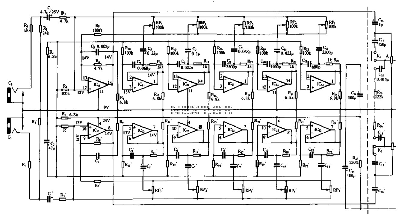
Figure 1-98 illustrates a double five-band equalizer circuit featuring a secondary connection. In this configuration, IC1 and IC14 serve as voltage amplifiers for each channel of the equalizer. The circuit also includes IC11, IC24, IC2, IC34, IC31, IC12, IC23,...