
usb power supply with lm2575
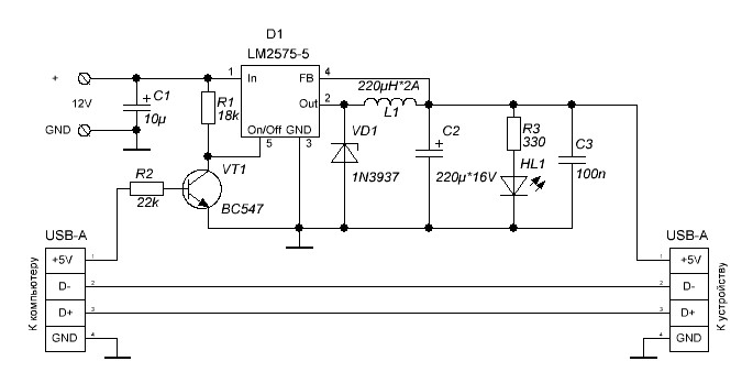
The additional power supply for USB devices is designed to enhance the power availability for devices that may require more current than what standard USB ports can provide. This circuit typically includes a voltage regulator, a transformer, and various passive components to ensure stable and efficient operation.
The circuit diagram usually features a step-down transformer that converts the AC mains voltage to a lower AC voltage suitable for the USB power requirements. Following the transformer, a bridge rectifier is employed to convert the AC voltage into DC voltage. Capacitors are placed at the output of the rectifier to smooth the rectified voltage, reducing ripple and providing a steady DC output.
A voltage regulator, such as the LM7805, is commonly used to maintain the output voltage at a stable 5V, which is the standard operating voltage for USB devices. Additional capacitors may be included at the input and output of the voltage regulator to enhance stability and transient response.
The circuit may also incorporate protection features, such as fuses or resettable polyfuses, to prevent damage to the power supply and connected devices in case of overload or short circuits. Furthermore, indicator LEDs can be added to signify when the power supply is active.
Overall, this additional power supply circuit is essential for powering USB devices that demand higher current levels, ensuring reliable operation and safety.Additional Power Supply for USB Devices power supply. Go to that page to read the explanation about above power supply related circuit diagram. 🔗 External reference
Related Circuits
This AC to DC power supply can output 5A in continuous operation and 12A peak current. This type of DC power supply utilizes a PCB, allowing for the use of two case types. The described AC to DC power supply...
In previous discussions, it was mentioned that several ATMEL ATMEGA16 processors were resoldered. A decision was made to create a useful application utilizing this microcontroller. Given that this controller offers increased ROM and RAM capacity, high-level programming in C...
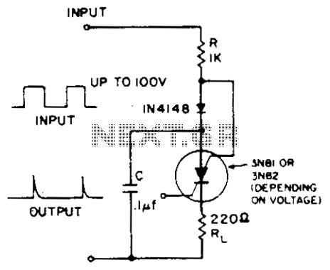
A positive-going input charges capacitor C through the IN4148 diode and resistor R. The diode ensures that the silicon-controlled switch (SCS) remains off. A negative-going input provides anode-gate current, which triggers the SCS, allowing capacitor C to discharge through...
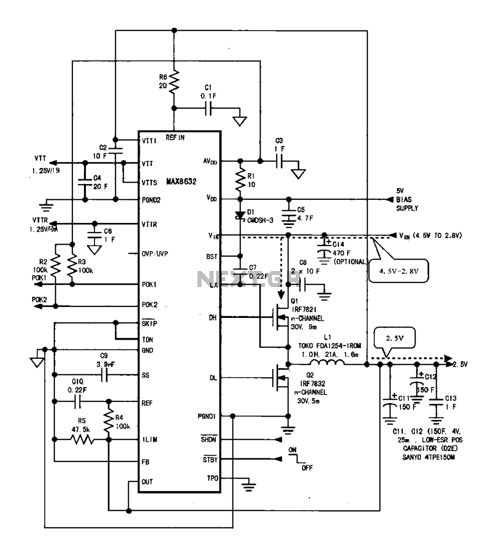
DDR memory power supply circuit. This circuit illustrates the power supply configuration for notebook DDR memory, utilizing the MAX8632 power control circuit chip. The power supply terminal VDD is connected to the voltage detection point 1. The battery DC...
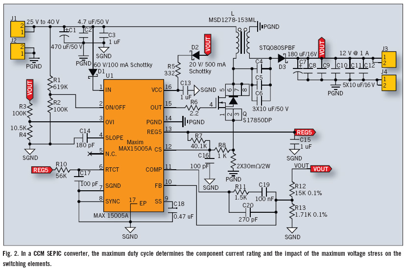
The Single-Ended Primary Inductance Converter (SEPIC) topology is an effective solution for automotive power systems that necessitate an output voltage that falls between the low and high values of the input voltage. The SEPIC topology is suitable for this...
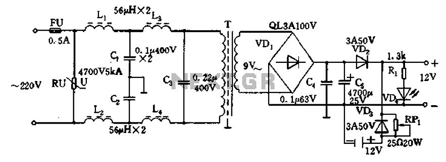
12V DC power supply circuit. A typical 12V DC power supply circuit includes a transformer that converts mains voltage to the required 12V AC output. It features a full-wave rectifier and a capacitor filter. The circuit typically incorporates a...