
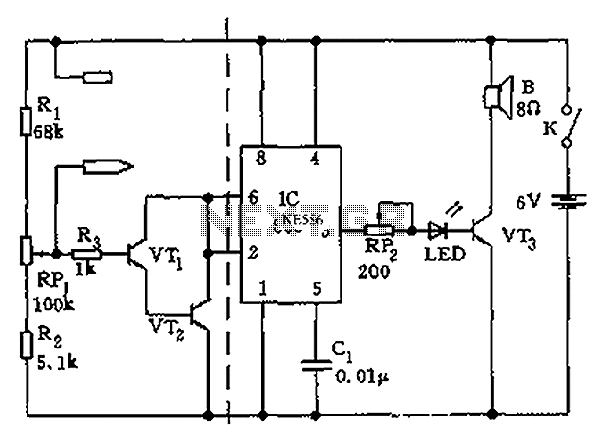
555 capacitance frequency transistor-line detector
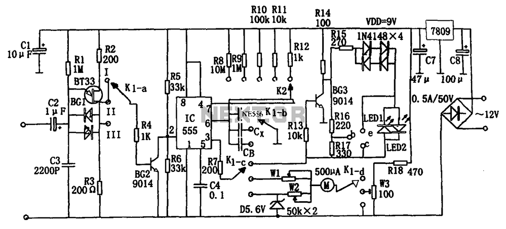
The described frequency detection circuit is an essential tool for measuring capacitance and frequency through a systematic approach involving a relaxation oscillator and a transistor testing mechanism. The use of a 555 timer provides a stable timing reference, while the adjustable resistors R8 to R12 allow for fine-tuning of the pulse width in relation to the measured capacitance Cx. The incorporation of the K1 switch facilitates user interaction, enabling the selection of measurement modes—either capacitance detection or frequency measurement.
In the capacitance measurement mode, the circuit's design ensures that as the capacitance increases, the output pulse width also extends, which can be directly correlated to the average output current. This characteristic is crucial for applications requiring precise capacitance values. The relaxation oscillator formed by BG1, R1, and C3 generates a consistent pulse train that serves as the triggering mechanism for the IC, ensuring reliable operation.
When measuring frequency, the circuit maintains a fixed output width, allowing for consistent readings across varying input signal frequencies. This feature is particularly valuable in applications where frequency stability is critical. The online transistor testing functionality provides a straightforward means of assessing transistor health, with LED indicators offering instant feedback on operational status.
Overall, this frequency detecting circuit exemplifies a well-integrated design that combines capacitance measurement, frequency analysis, and transistor testing into a single, versatile platform, making it an invaluable asset in electronic testing and diagnostics. The design principles employed ensure robustness and reliability, catering to a range of electronic applications. As shown for the capacitor, the frequency detecting circuit transistor line. Can be converted by adjusting the preset switch K1 when this detector capacitance, frequency, trans istor testing. The K1 placed II detectable capacitance. 555 and R8 ~ R12 and measured capacitance Cx composition single stabilizing circuit, Cx capacity is increased, the pulse width, ie td 1.1 (R8 ~ R12) Cx longer, the greater the current average, indicating that the corresponding header greater. Circuit BG1 single junction transistor with R1, C3 composition relaxation oscillator, the oscillation output pulse signal as a trigger pulse of the IC.
The K1 placed III frequency measurements can be carried out. At this one-shot circuit IC output td signal 1.1 (R8 ~ R12) CB fixed value width. The higher the frequency of the input signal. Frequency IC is triggered, the more the greater the average current, the greater the corresponding table header indicates. The K1 place I can be online test transistor. The principle is similar to the detection capacitor. Circuit transistor BG1 complete positive and negative power conversion. With IC output high and low alternating changes, if the light-emitting diodes LED1, LED2 turn light, then the transistor is good, otherwise the transistor is bad.
Related Circuits
The iPod Shuffle has malfunctioned, likely due to a failure in the controller chip for the mini jack, resulting in the inability to detect the charger, PC connection, or headphones. The arc must be kept short to minimize distortions...
To determine whether it is freezing, it is necessary to measure the temperature accurately using a reliable temperature sensor. The LM35CZ, which operates between -40 to 110 °C, has been chosen for this purpose. This sensor generates an output...
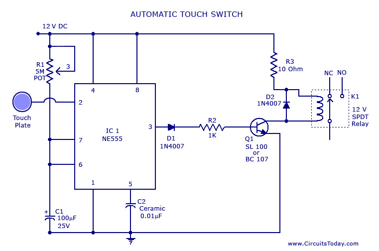
A touch switch circuit schematic utilizing a 555 integrated circuit (IC). When the touch plate is activated, a relay is switched ON for a predetermined duration, which can also be adjusted. The touch switch circuit employs a 555 timer IC...
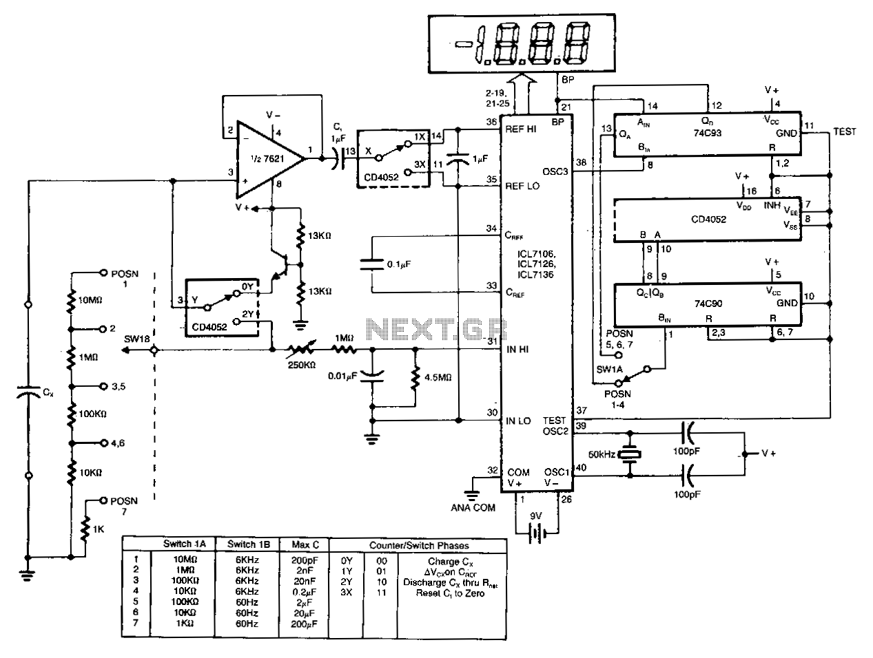
The circuit charges and discharges a capacitor at a crystal-controlled rate and stores the change in voltage achieved on a sample-and-difference amplifier. The current flowing during the discharge cycle is averaged and ratiometrically measured in the analog-to-digital converter (ADC)...
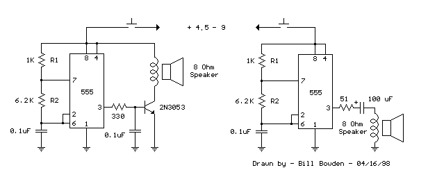
This is a basic 555 square wave oscillator designed to generate a 1 kHz tone for an 8-ohm speaker. In the circuit, the speaker is isolated from the oscillator by an NPN medium power transistor, which supplies more current...
The apparatus consists of a cavers point detection circuit and a triggering display circuit. The cavers instrument functions as a test probe, which, when held in one hand, can detect acupuncture points by touching the skin with another probe....