
Power Amplifiers

The amplifier design features a minimalist approach to protection circuitry, which is a notable characteristic. The absence of extensive protective measures such as thermal shutdown, overcurrent protection, or DC offset protection could pose risks under certain operating conditions. The inclusion of a short turn-on delay is a beneficial feature, designed to prevent thumps that may occur during power-up, which can be detrimental to both the amplifier and connected speakers.
The line fuses serve as a basic safeguard against overcurrent situations, but their limited scope may not be sufficient for all scenarios. Users should exercise caution, as the lack of comprehensive protection could lead to severe consequences in the event of component failure or other unforeseen issues. Despite these risks, the choice of robust speakers designed to withstand high power levels mitigates some of the potential dangers associated with the amplifier's operation.
The construction of the amplifier utilizes custom double-sided printed circuit boards (PCBs), which have been created using the toner transfer method. This method allows for a high level of customization and can lead to improved performance characteristics, as the layout can be optimized for the specific requirements of the amplifier circuit. The populated bridging adapter indicates a thoughtful design that allows for flexibility in speaker configurations.
The performance metrics of the amplifier are impressive, with a power output of 150 RMS Watts per channel into 8-ohm loads and 225 Watts into 4 ohms, making it suitable for a variety of audio applications. The significant improvement in sound quality, characterized by a more dynamic audio experience and enhanced soundstage, suggests that the design choices have successfully prioritized audio fidelity.
Thermal performance is another critical aspect of the amplifier's design. Operating at lower temperatures than previous models indicates efficient heat dissipation, which is crucial for maintaining reliability and longevity. The ability to function without active cooling under high load conditions is an advantage that enhances usability and reduces noise from cooling fans.
Future iterations of the amplifier will focus on refining the design further, potentially integrating additional features while maintaining the core benefits that have been established in the first unit. The commitment to ongoing updates and improvements reflects a proactive approach to product development in the audio engineering field.Note that there is very little in the way of protection circuitry and fuses in this amplifier. There is a short turn-on delay for the output power supply to minimise thumps, and a couple of line fuses, but no other protection. This is not recommended for most applications, since any problems caused by accident or parts failure can potentially caus
e a huge amount of damage, up to and including complete destruction of the amplifier and any speakers that may be connected. However, the speakers that will be used with these particular amplifiers are almost indestructable, and the risk of catastrophic amplifier failure is more than compensated for with the better sound achieved by not including the extra circuitry in this case.
Below is a picture of the bare printed circuit boards for the amplifer sections, as well as the bridging adapter, fully populated. These are home-made double sided pc boards created with the toner transfer method. And finally, pictures of the finished amplifier. The project has been a great success so far, with the first amplifier achieving or surpassing the original design goals.
The sound is much more dynamic than the original, with sounds seeming to leap right out at you. Detailing is far superior, with a wider, deeper, very stable soundstage. And the amplifier runs much cooler, only getting a bit warm when run hard, as opposed to the original PS Audio amplifiers which required fan cooling at higher volumes. Power output is measured at 150 RMS Watts per channel into 8 ohm loads and 225 Watts into 4 ohms. This first amplifier will now be auditioned at length, with further refinements and improvements made.
Eventually, the second amplifier will be constructed to match the first one, including any modifications. Updates, as always, will be added as they become available! 🔗 External reference
Related Circuits
The amplifier drives a pair of loudspeakers using two LM3876 integrated power amp ICs (50 watts per channel), or a pair of headphones via a Meier crossfeed filter and an OPA2134 dual opamp. It provides four switchable line level...
The IEEE 802.3af standard defines the interaction between power-sourcing equipment and powered devices within a power-over-Ethernet system. The IEEE 802.3af standard, also known as Power over Ethernet (PoE), specifies the mechanisms by which electrical power is transmitted alongside data over...
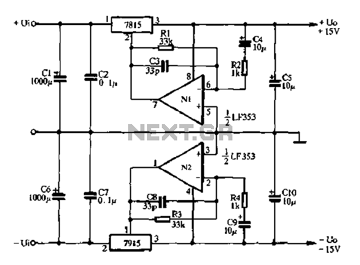
15V active servo power supply circuit The 15V active servo power supply circuit is designed to provide a stable and regulated output voltage of 15 volts, suitable for powering servo motors and other related devices. This circuit typically employs a...
High-energy capacitors can produce hundreds of amps when short-circuited, potentially causing severe burns, fires, and property damage. It is essential to be aware of these hazards when using such capacitors and to take precautions to avoid accidental short-circuits. The...
Four simple 12V power supply circuits are designed to provide output voltages close to 12V. The first power supply circuit utilizes a BD139 transistor, a zener diode, and several passive components. Each schematic is straightforward to assemble and will...
Buffers are a specific category of amplifiers, and power buffers are a subset of power amplifiers. The defining characteristics of all buffers include unity gain and a low impedance output, ideally accompanied by low distortion. When examining commercially available...