
Power failure emergency lights automatically converter circuit diagram
The described application circuit is designed to provide reliable lighting solutions in critical environments where continuous illumination is essential. The circuit incorporates an LCE (Lighting Control Equipment) module that serves as the core component for managing the transition between normal and emergency lighting modes.
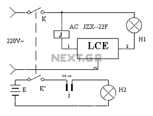
In normal operation, when the main power supply is active, H1 (normal lighting equipment) operates as intended, providing adequate illumination for various tasks. The LCE module continuously monitors the power supply status. Upon detecting a power failure, the module initiates a switch to H2 (emergency lighting) mode. This transition is seamless, ensuring that there is no perceptible interruption in lighting for users, which is particularly vital in sensitive situations such as surgical procedures.
The circuit design typically includes a power source, a relay or a solid-state switch for toggling between H1 and H2, and appropriate control circuitry that manages the LCE module's response to power fluctuations. The emergency lighting system can be powered by a backup battery or an alternative power source, ensuring that H2 is reliably activated during outages.
In addition, the circuit may feature indicators or alarms to notify users of power status, ensuring that personnel are aware of any changes in lighting conditions. This design is crucial for maintaining safety and operational efficiency in environments where lighting is critical, such as hospitals, laboratories, and emergency response facilities. The overall configuration ensures that the system meets regulatory standards for emergency lighting, thereby enhancing the safety and functionality of the application.Application circuit works the device as shown below, a number of special occasions allowed intermittent lighting (eg doing surgery, etc.), making use of LCE module blackout eme rgency lighting converter automatically after a power failure lighting can be achieved without interruption effect. Wherein H1 is the norm lighting equipment; H2 is lighting when emergency power.
Related Circuits
Every dedicated DIY enthusiast creates their own electronic dice using LEDs as indicators. This eliminates the need to physically roll dice; simply pressing a button activates the electronic mechanism. The design incorporates safeguards to prevent manipulation for improved outcomes,...
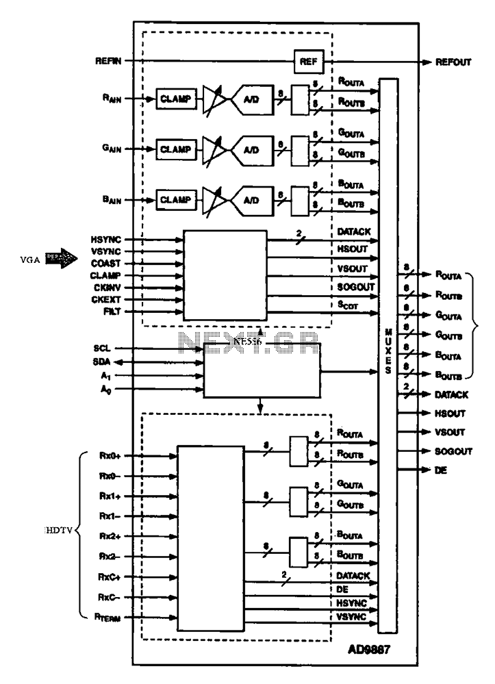
The AD9887, a commonly used video A/D converter for liquid crystal televisions, is capable of converting analog red, green, and blue (R, G, B) signals into digital signal outputs. The AD9887 is a high-performance analog-to-digital converter (ADC) specifically designed for...
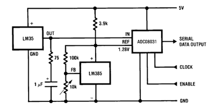
The circuit illustrates a Temperature to Digital Converter diagram utilizing the LM35 sensor, which includes a beneficial bypass capacitor connected from VIN to ground and a series RC damper. The described circuit employs the LM35 temperature sensor, a precision integrated...
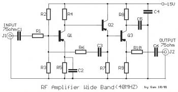
This is a 40 MHz RF amplifier circuit. The sensitivity of a receiver can be significantly enhanced by integrating this circuit between the receiver and the antenna. The amplifier does not utilize resonant circuits and is suitable for both...
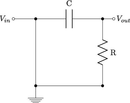
This guide aims to demonstrate the construction of various filter circuits, specifically low pass and high pass filters, along with additional details. The construction of filter circuits is essential in many electronic applications, as they allow for the selective passage...
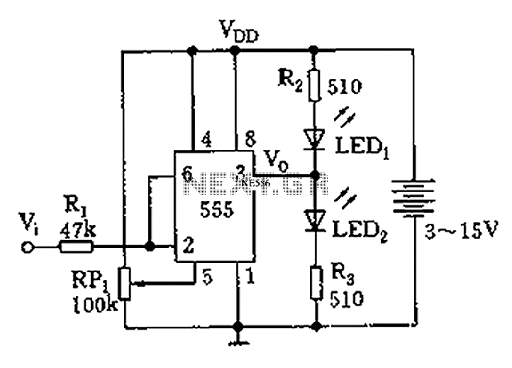
Figure 555 illustrates a simple logic circuit test lead. The test pen utilizes the 555 timer IC as its core component, incorporating a Schmitt trigger to assess the logic state of digital circuits. The circuit has two outputs: when...