
Power LED Driver Circuit
This power LED driver circuit is designed to efficiently drive high-power LEDs with a stable output. The circuit typically consists of a few key components: a power supply, a current regulator, and the LED itself.
The power supply provides the necessary voltage and current for the operation of the circuit. It is important to select a power supply that can deliver sufficient current while maintaining a stable output voltage. A common choice for such applications is a DC power supply with a voltage rating that matches the forward voltage of the LED.
The current regulator is a crucial component that ensures the LED operates within its specified current limits. This can be implemented using a linear regulator or a switching regulator, depending on the efficiency requirements of the application. For linear regulation, a transistor can be used in conjunction with a resistor to set the desired current level. In contrast, a switching regulator can offer higher efficiency and is particularly advantageous for battery-powered applications.
The LED itself should be selected based on the desired brightness and color. High-power LEDs typically require careful thermal management, so the circuit may also include a heat sink to dissipate excess heat generated during operation.
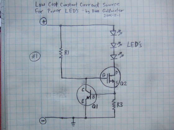
In summary, this power LED driver circuit is a fundamental design that combines a power supply, current regulation, and thermal management to effectively drive high-power LEDs, ensuring optimal performance and longevity.Here`s a really simple and inexpensive Power LED driver circuit. 🔗 External reference
Related Circuits
S1 and S2 are normally open, push-to-close, momentary switches. The diodes may be red or green and serve solely as indicators of direction. The TIP31 transistors may need to be adjusted based on the motor specifications. It is important...
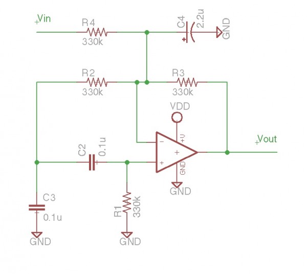
It is essentially an all-pass filter with two additional components: a capacitor and a resistor, which produces percussion sounds. A schematic of the unmodified all-pass filter circuit, a waveform captured via Audacity, and a short audio sample featuring a...
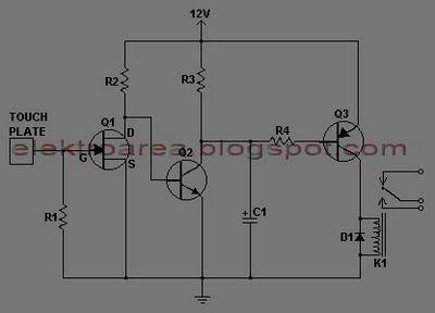
This document describes a series of touch switches that utilize only three transistors. These touch-based transistor switches can activate a load simply by the user touching a metal plate. They are designed to directly switch a relay, enabling operation...
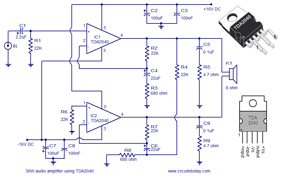
The individual is new to electronics but enjoys experimentation. They plan to create a small guitar amplifier based on a 30 Watt design, specifically the single 12VDC version referenced in comments. The intention is to incorporate a preamplifier to...
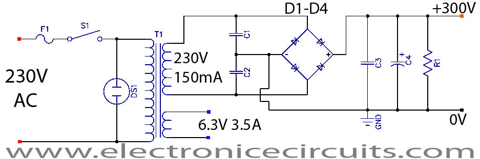
This project is a successful vacuum tube amplifier utilizing a 6V6GT output pentode configured in triode mode, producing approximately 4.5 watts of output power. The design features a single-ended audio amplifier with a resistive input network, a driver stage,...
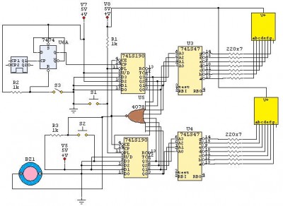
This is a 24-second countdown timer circuit designed for automatic control of electronic loads. The timer circuit utilizes fast 74LS Schottky integrated circuits (ICs). A 24-second countdown begins when switch S3 is off and switch S2 is pressed. Switch...