
DC Motor Control Circuit
This circuit utilizes two momentary push-button switches, S1 and S2, which are configured to control the direction of a small DC motor used for curtain operation. The switches are normally open, meaning they only complete the circuit when pressed. This design allows for manual control, providing the user with the flexibility to adjust the curtains to their desired position, thereby regulating light entry into a room.
The circuit incorporates TIP31 transistors which act as electronic switches that control the power to the motor. The selection of these transistors may need to be adjusted based on the motor's specifications, particularly in terms of current handling capacity. It is critical to recognize that when the motor operates under load, it draws more current; thus, ensuring that the transistors can handle the maximum current is essential for reliable operation.
Additionally, the circuit includes four diodes arranged around the motor to protect against back electromotive force (back EMF) generated when the motor is turned off. This back EMF can potentially damage other components in the circuit. The choice of diodes, such as the 1N4001 for a 12V motor drawing 1 amp, is based on the need to effectively handle the reverse voltage produced during motor operation.
Overall, this circuit provides an effective solution for controlling curtain movement with a manual interface, ensuring user flexibility while incorporating essential protective features to safeguard the components involved.Here, S1 and S2 are normally open, push to close, press button switches. The diodes can be red or green and are there only to indicate direction. You may need to alter the TIP31 transistors depending on the motor being used. Remember, running under load draws more current. This circuit was built to operate a small motor used for opening and closi ng a pair of curtains. As an advantage over automatic closing and opening systems, you have control of how much, or how little light to let into a room. The four diodes surriunding the motor, are back EMF diodes. They are chosen to suit the motor. For a 12V motor drawing 1amp under load, I use 1N4001 diodes. We aim to transmit more information by carrying articles. Please send us an E-mail to wanghuali@hqew. net within 15 days if we are involved in the problems of article content, copyright or other problems.
We will delete it soon. 🔗 External reference
Related Circuits
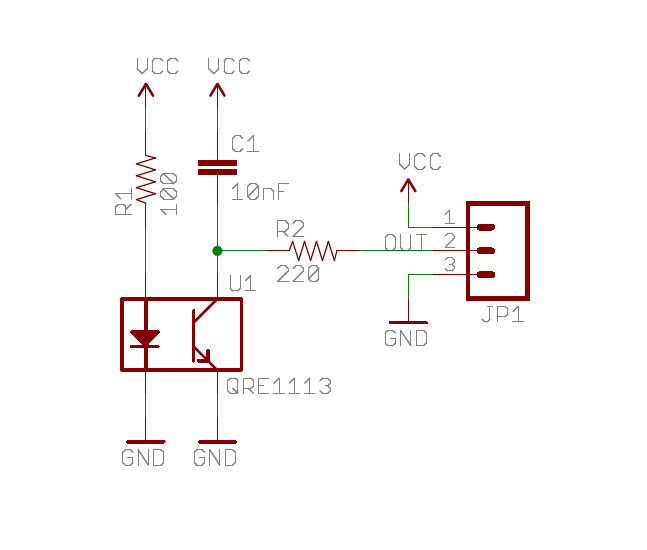
A real-time clock turns off the counter at night to conserve power. When a bee crosses under the LED, the light is reflected back to the sensor, which is a phototransistor, and triggers a digital input to the Arduino...
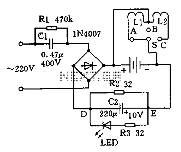
Charging the battery in a slow manner (using a low charging current over an extended period) is the most economical and safest method. The design of the trickle charger should focus on two key points: firstly, the use of...
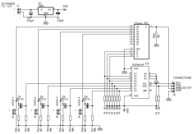
This page describes a battery tester designed to characterize batteries and save the results on a microSD card. The battery tester circuit is engineered to evaluate the performance and capacity of various battery types, providing accurate and reliable data storage...
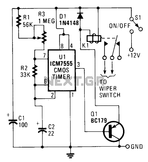
U1 is configured to operate in the standard astable mode, functioning as a relaxation oscillator. When power is applied, C2 initially charges through R1, R2, and R3 to two-thirds of the supply voltage. At this point, U1 detects that...
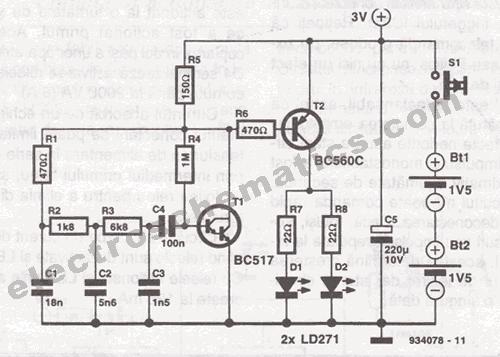
This infrared transmitter is designed for use with an infrared receiver. It operates using either two 1.5V batteries or a 3V lithium battery, allowing for a compact infrared communication system. The infrared transmitter circuit typically consists of an infrared LED,...
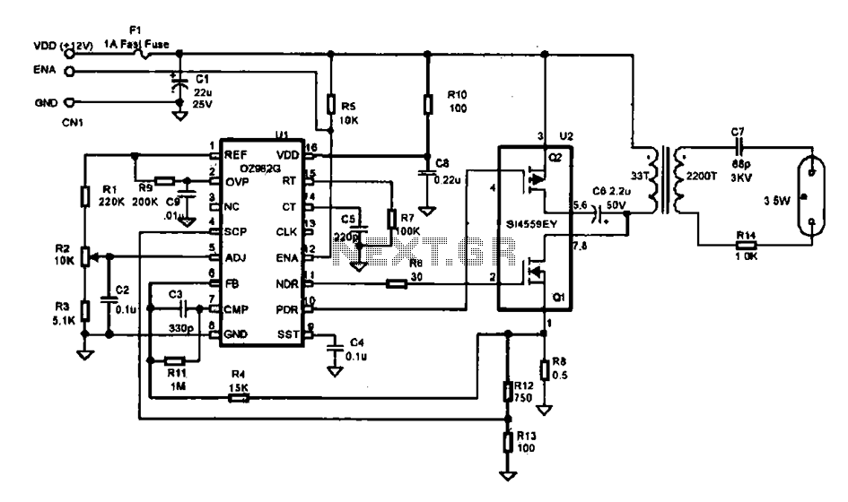
This document describes an efficient inverter control circuit designed for use as an LCD backlight power supply. The circuit is primarily managed by the chip UL (02962G), which interfaces with a driving field-effect transistor (U2), a voltage transformer, the...
Warning: include(partials/cookie-banner.php): Failed to open stream: Permission denied in /var/www/html/nextgr/view-circuit.php on line 713
Warning: include(): Failed opening 'partials/cookie-banner.php' for inclusion (include_path='.:/usr/share/php') in /var/www/html/nextgr/view-circuit.php on line 713