
touch switch circuit with 3 transistors
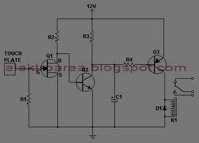
This touch switch circuit operates on the principle of capacitive sensing, where the presence of a finger near the metal plate alters the capacitance of the circuit, triggering the transistors to switch states. The three transistors are configured in a manner that allows one to act as a sensor, while the other two form a bistable flip-flop arrangement, enabling the latching function.
In operation, when a user touches the metal plate, the first transistor detects the change in capacitance and activates the second transistor, which in turn energizes the relay. This relay can handle high voltage and current loads, making it suitable for controlling various electrical devices. The latching relay maintains its state even after the user removes their finger from the touch pad, providing a simple and effective on/off control mechanism.
The design's simplicity and use of standard components make it highly accessible for prototyping and implementation in various applications. The touch pad can be customized in size and shape to fit specific design requirements, and the use of a 12V power supply ensures compatibility with a wide range of devices. This circuit is particularly advantageous in environments where physical switches may be vulnerable to wear, corrosion, or other forms of damage, thus enhancing the overall reliability and longevity of the control system.Here is a series of Touch Switch using only 3 transistors, this touch-based transistor switches can activate a load simply by the user touching a metal plate. It is designed to directly switch a relay to allow it to be used with large loads. As it uses only a few commonly available transistors and a 12V supply, it is ideal for hostile environments
where mechanical switches would be damaged. Using a latching relay and two of these circuits, a simple two pad "touch on / touch off" arrangement can be made. The touch pad can be most easily made by cutting a small square of PCB material and then soldering on a single wire.
Alternatively, something like a penny glued to a plastic backing will do the job. 🔗 External reference
Related Circuits
A remote control light switch designed to fit into an existing light switch panel requires a 3.3V DC power supply for its electronics. However, the panel contains only two wires: one live wire and one wire that connects to...
Configured with capacitive coupling by inserting a small capacitor between the phototransistor and the bipolar transistor, this relay circuit will respond only to rapid changes. This relay circuit utilizes capacitive coupling to enhance its responsiveness to fast signal changes. The...

The circuit consists of a 5V TOP414G isolated switching power supply with a 2A output. C1 serves as the input filter capacitor. The circuit includes a voltage clamp protection mechanism composed of VD1. The control terminal is connected to...
Control monitoring equipment at a TV repeater site is designed to accept commands sent as DTMF tones over the repeater's audio channel. It is capable of switching either AV signals or power supply feeds with currents up to 1...
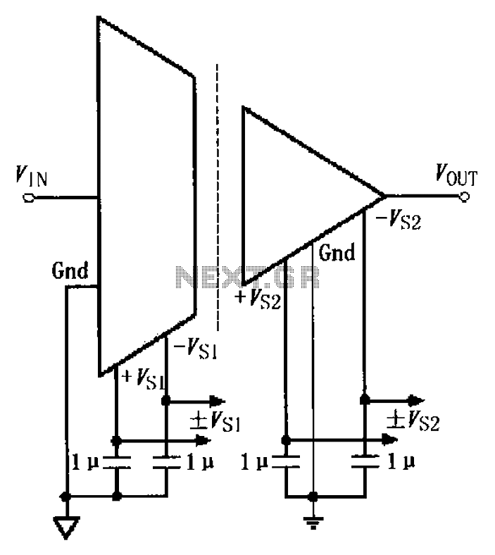
The basic connection circuit for the ISO122/124 includes power and signal connections. Each supply terminal of the ISO122/124 must be equipped with a 1 µF tantalum capacitor serving as a bypass filter. It is important to position the printed...
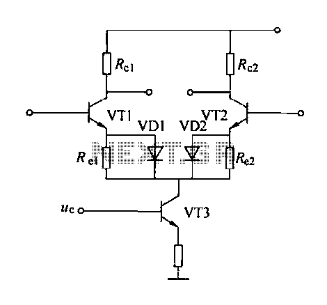
A controllable gain amplifier functions as an automatic gain control circuit within the execution unit. The primary methods for controlling the amplifier's gain involve two approaches: one is by adjusting certain parameters of the amplifier itself, such as emitter...
Warning: include(partials/cookie-banner.php): Failed to open stream: Permission denied in /var/www/html/nextgr/view-circuit.php on line 713
Warning: include(): Failed opening 'partials/cookie-banner.php' for inclusion (include_path='.:/usr/share/php') in /var/www/html/nextgr/view-circuit.php on line 713