
Power-line frequency meter
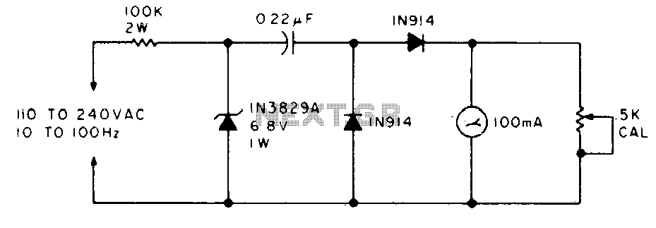
The described circuit functions as a frequency meter, utilizing a straightforward analog approach to convert the frequency of a power generator into a readable current output. The circuit begins with the input of sine wave signals from the power generator, which are characterized by their smooth periodic oscillations. The first stage of the circuit employs a 100K ohm resistor in conjunction with a 6.8 V zener diode to convert these sine waves into square waves. The zener diode serves to clip the peaks of the sine wave, allowing only the necessary voltage levels to pass through, while the resistor helps to limit the current and stabilize the operation of the zener.
Following the conversion to square waves, the circuit incorporates a capacitor that differentiates the square wave signal. Differentiation in this context refers to the process of measuring the rate of change of the square wave, which results in a pulse-like output that is proportional to the frequency of the incoming signal. This pulse output is then fed into a set of diodes that average the current, effectively smoothing out the fluctuations to provide a steady average current that correlates with the frequency of the input signal.
The average current produced by this stage is directly proportional to the frequency of the incoming sine waves, allowing for a simple and effective means of measuring frequency. This average current can be displayed on a 100 mA analog meter, providing a visual representation of the frequency being measured.
For calibration purposes, the circuit is designed to be connected to a 60 Hz power line. By adjusting the 5 K potentiometer, the output can be fine-tuned to ensure that the meter reads exactly 60 mA when the circuit is exposed to the standard 60 Hz frequency. This calibration step is crucial for ensuring accurate frequency measurements across different operational conditions. Overall, this circuit provides a reliable method for frequency measurement in power generation applications.The meter will indicate the frequency from a power generator. Incoming sine waves are converted to square waves by the 100K resistor and the 6,8 V zener. The square wave is differentiated by the capacitor and the current is averaged by the diodes. The average current is almost exactly proportional to the frequency and can be read directly on a 100 mA meter To calibrate, hook the circuit up to a 60 Hz poweraline and adjust the 5 K pot to read 60 mA. 🔗 External reference
Related Circuits
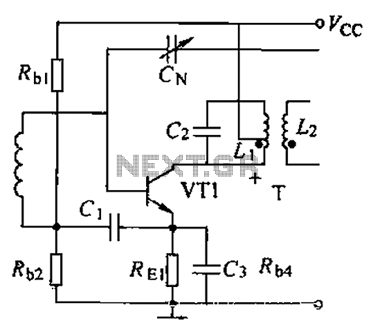
A common intermediate frequency amplifier circuit is presented, along with its components and parameters. The reference values for the components are as follows: 1) Transistors: VT1 to 3DG19, Vcc = 6V. 2) Resistance values: R1 = 50 kΩ, R2...
This transmitter originated as a conventional shunt-fed Hartley oscillator for 80 meters, utilizing a pair of 27 triodes connected in parallel. With 300 VDC applied to the plates of the 27s, it produced approximately 4 watts of output with...
For an introduction to the liquid-level inclinometer and a description of the apparatus and early work on the instrument, refer to Inclinometer Performance. This documentation records day-to-day work on the instrument from February 2008 onwards. Section headings are provided...

The Wien bridge oscillator generates frequencies of 1 Hz and from 2 to 20 Hz in 2 Hz increments. The maximum output amplitude is 3 volts RMS or 8 volts peak-to-peak. A potentiometer and switch attenuator enable the output...
A technique for measuring frequencies across a wide range with acceptable accuracy using a PC is described. This method involves measuring the period of a complete wave at low frequencies to calculate frequency from the measured time period. Cascaded...
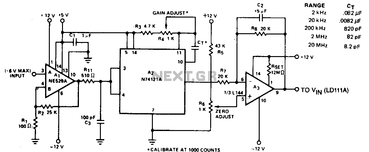
The circuit converts frequency to voltage by taking the average DC value of the pulses from the 74121 monostable multivibrator. The one-shot is triggered by the positive-going AC signal at the input of the 529 comparator. The amplifier functions...