
Very low frequency generator

The Wien bridge oscillator is a type of electronic oscillator that produces sine waves. It is based on a bridge circuit that includes resistors and capacitors arranged in a specific configuration. The oscillator operates by balancing the bridge circuit, allowing it to generate a stable frequency output.
In this design, the frequency range is specified to start at 1 Hz and extend to 20 Hz, with the ability to tune in 2 Hz steps. This is achieved by adjusting the values of the resistors and capacitors in the bridge circuit. The frequency can be fine-tuned for applications requiring precise frequency generation, such as in audio testing or signal processing.
The output amplitude is specified as a maximum of 3 volts RMS, which corresponds to 8 volts peak-to-peak. This output level is suitable for a variety of applications, including driving other circuits or providing a reference signal.
To facilitate flexibility in output level, a potentiometer (variable resistor) combined with a switch is incorporated into the design. This allows for precise attenuation of the output signal, enabling the user to set the output level to any desired value within a range of 5 decades. This feature is particularly useful for applications requiring varying signal strengths or for interfacing with other equipment that may have different input sensitivity requirements.
Overall, the Wien bridge oscillator with an adjustable output level provides a versatile solution for generating low-frequency sine wave signals with high precision and control.Wien bridge oscillator generates frequencies of 1 Hz and 2 to 20 Hz in 2 Hz steps. Maximum output amplitude is 3 volts rms of 8 volts peak-to-peak A pot-and-switch attenuator allows the output level to be set with a fair degree of precision to any value within a range of 5 decades. 🔗 External reference
Related Circuits
A standard 12-volt automotive electrical system can be viewed as a robust yet unreliable source of low-voltage DC current. Any mobile PC installation should encompass several features, as automotive systems must adhere to strict electrical standards. The starter motor...
Here is an updated schematic featuring the RF Solutions receiver along with several minor additions. The design includes additional circuitry to manage the signals effectively. The updated schematic incorporates an RF Solutions receiver, which is essential for receiving radio frequency...
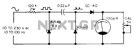
The meter utilizes a zener diode to convert input sine waves into square waves. After calibration with a 5 k ohm potentiometer, the 100 µ meter provides a direct reading in hertz. The circuit employs a zener diode as a...
This simple LED tester consists of a current source with a potentiometer that can be used to adjust the current. The current source is implemented using a TL081 operational amplifier. The output current from the op-amp flows through the...

This project is designed to provide security for personal belongings left on a beach towel while swimming or engaging in other activities. The project involves creating a portable electronic alarm system that can be easily set up on a...
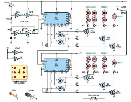
This simple dual digital dice is based on three low-cost integrated circuits (ICs), a few transistors, and several light-emitting diodes (LEDs). IC1a and IC1b function as oscillators with a specific frequency. The dual digital dice circuit utilizes three low-cost integrated...
Warning: include(partials/cookie-banner.php): Failed to open stream: Permission denied in /var/www/html/nextgr/view-circuit.php on line 713
Warning: include(): Failed opening 'partials/cookie-banner.php' for inclusion (include_path='.:/usr/share/php') in /var/www/html/nextgr/view-circuit.php on line 713