
POWER MOSFET INVERTER

The inverter circuit described is designed to convert low-voltage DC into high-voltage AC or DC, suitable for various applications requiring high voltage. The use of a transformer with reversed windings allows flexibility in voltage conversion, enabling the circuit to adapt to different input and output voltage requirements.
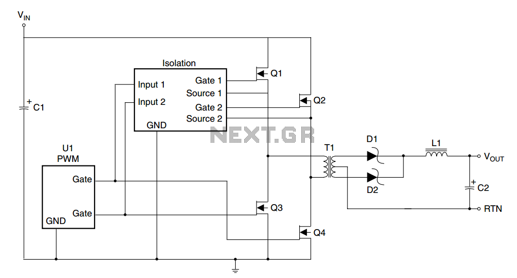
The power FETs, Q1 and Q2, are critical components in the inverter's operation, acting as switching devices that control the flow of current through the transformer. Proper thermal management is crucial for these transistors, as they can generate significant heat during operation. The inclusion of heat sinks is necessary to maintain their operational integrity and prevent thermal failure.
Capacitors C1 and C2 play a vital role in protecting the circuit from voltage spikes, which can occur due to the rapid switching of the FETs. These capacitors help to smooth out fluctuations in voltage and provide stability to the output, ensuring that the inverter operates reliably under varying load conditions.
Overall, this inverter circuit is a robust solution for applications requiring high-voltage output, combining effective voltage transformation with essential protective features to enhance performance and reliability. Proper selection of components and attention to thermal management are key factors in optimizing the circuit's functionality.This inverter can deliver high-voltage ac or dc, with a rectifier and filter, up to several hundred volts. The secondary and primary of T1-a 12. 6 to 440 V power transformer, respectively-are reversed; e. g. , the primary becomes the secondary and the secondary becomes the primary. Transistors Q1 and Q2 can be any power FET. Be sure to heat sink Q1 a nd Q2. Capacitors C1 and C2 are used as spike suppressors. 🔗 External reference
Related Circuits
A typical specification can range from a low of 36V to a high of 72V, with a nominal value of 48V. In some designs, transients exceeding 100V must be considered. Most of these designs will require input to output...
Using the versatile L200 voltage regulator, this power supply has independent voltage and current limits. The mains transformer has a 12volt, 2 amp rated secondary, the primary winding should equal the electricity supply in your country, which is 240V...
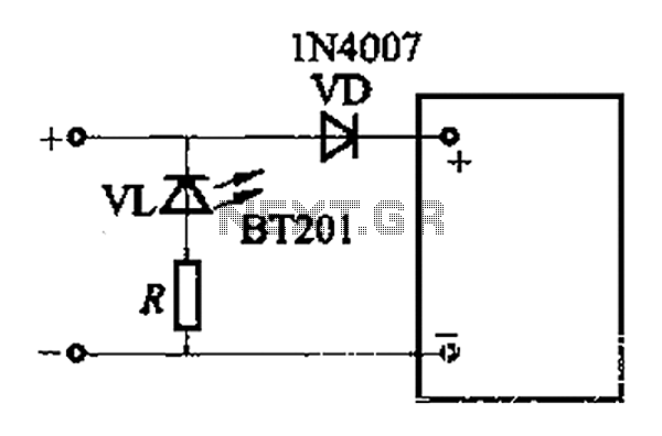
The adjustment potentiometer RP allows for modification of the over-voltage limit setting. In the event of reversed polarity in the DC power supply, there is a risk of damaging equipment components. To mitigate this risk, a reverse polarity protection...
More: A comprehensive electronic schematic involves the representation of electrical components and their interconnections in a circuit. Each component is typically represented by standardized symbols, and the connections between them are depicted using lines. The schematic provides essential information...
Quasi square wave resonant converters, also referred to as quasi resonant (QR) converters, facilitate the design of flyback Switch Mode Power Supplies (SMPS) with diminished Electro Magnetic Interference (EMI) and enhanced efficiency. Due to their low noise generation, QR...
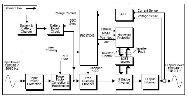
The UPS (Uninterruptible Power Supply) Reference Design offers a pre-designed uninterruptible power supply solution utilizing the flexibility of the PIC17C43 microcontroller. This microcontroller is noted for its low-cost and high-performance capabilities, which are not typically found in other microcontrollers....