
UPS (Uninterruptible Power Supply) Reference Design
 Reference Design")
The UPS reference design incorporates several critical components and subsystems that work in tandem to deliver reliable and efficient power management. The PIC17C43 microcontroller serves as the control hub, executing firmware that governs the operation of the inverter and the overall UPS functionality. The PWM signal generated by the microcontroller is essential for controlling the inverter, which is responsible for converting DC power to AC power with a sine wave output. The filtering stage following the inverter ensures that the output waveform meets the necessary quality standards for sensitive electronic devices.
The Power Factor Correction module plays a pivotal role in optimizing energy consumption by ensuring that the input current remains in phase with the input voltage. This minimizes reactive power and enhances the overall efficiency of the UPS system. The rectification process transforms the incoming AC power into regulated DC power, which is crucial for the operation of various components within the UPS.
The design's fault detection and signaling capabilities are vital for maintaining the integrity of the UPS operation. By continuously monitoring output parameters, the microcontroller can quickly respond to any anomalies, thereby protecting the system and connected loads. The use of zero-crossing detection facilitates seamless transitions in output phase, further enhancing the quality of the AC power supplied.
In summary, this UPS reference design exemplifies a sophisticated integration of microcontroller technology with power electronics, offering a robust solution for uninterruptible power supply applications. The flexibility inherent in the design allows for customization, making it suitable for a wide range of applications and user requirements.UPS (Uninterruptible Power Supply) Reference Design provides a ready-made uninterruptible power supply solution with the flexibility of a microcontroller - PIC17C43 that offers a low cost solution and high performance not found in other microcontrollers. The PIC17C43 ( datasheet ) microcontroller manages all the control of the UPS system. The PIC1 7C43 PWM controls an inverter whose output, when filtered, results in a sinusoidal AC output waveform. Fault signaling can be initiated internal or external to the PIC17C43 depending on the type of fault.
A fault will disable the entire inverter. The output voltage and current will be monitored by the PIC17C43 to make adjustments real-time to correct for DC offset and load changes. The PIC17C43 uses zero crossing for synchronization of input voltage/phase to output voltage/phase. All internal module synchronization is handled by the PIC17C43. The Uninterruptible Power Supply (UPS) is supplying power based on the input power, if the unit is plugged in, or based on the batteries.
The input power is filtered (when available) for common mode noise and is protected from surges/spikes by input power protection circuitry. Then the power goes into the power factor correction (PFC) module which forces the input current to be sinusoidal so that power utilization is more efficient.
The PFC module also rectifies the input AC power to produce voltage-regulated DC power which is used by the rest of the functional modules. This reference design is for guidance only, and it is anticipated that customers will modify parts of it.
The PIC16/17 family of microcontrollers offers a wide variety of options for a UPS design from the PIC16C72 to the PIC17C756. The PIC17C43 is the heart of this reference design (see the picture below). The high performance of the Harvard architecture gives the user the throughput needed for high quality sine wave generation.
The single-cycle multiply means faster program execution and response to waveform changes. Only 8 bits of the 10-bit PWM is needed to resolve a high quality output waveform. The PIC17C43 embedded software controls the operation of the AC sine wave generation. It is imperative that the loop response be fast enough to minimize distortion on the output wave. Therefore, the throughput of the microcontroller is a critical parameter. The UPS is an on-line device which normally will have the Power Factor Correction circuit feeding the Chopper, which then feeds the Inverter. If the input power should be lost, the Power Factor Correction circuit falls out of the power flow and the Battery Boost circuit automatically provides power to the Chopper.
In the Battery Boost circuit, the transistor pairs are connected in parallel for the purpose of handling high currents. The current transformer T2 is connected as shown to sense each pair`s current with just one transformer, i.
e. , to prevent it from saturating. The control for the 120V/240V relay (power switch) was not implemented. Wherever input power monitoring would take place, monitoring for 120 or 240V would also occur and switch the relay. These functions would be placed before the PFC circuit. / <7465> * * Filename: MAIN. C <7465> * * * Author: Dave Karipides * Company: APS, Inc. * Date: 3-3-97 * Compiled Using MPLAB-C Rev 1. 21 * <7465> * * * Include Files: * <7465> * * * The main routine calls all the functions for generating * an OPEN_LOOP or FEEDBACK sine wave of either 50 or 60 Hz.
* <7465> * * * Revisions: * 3/3/97 Added FEEDBACK LOOP * * <7465> */ / <7465> * * main() * * The main routine initializes the registers and loops * forever. All control is handled in the TMR0 INT * routine. * * * Input Variables: NONE * * Output Variables: NONE * * <7465> */ //#define OPEN_LOOP #define FEEDBACK //#define 50Hz #define 60Hz #pragma option v #include <17c43.
h> #include #ifdef OPEN_LOOP // This table yields Full VRMS input unsigned char const pwmtab[32] 🔗 External reference
Related Circuits
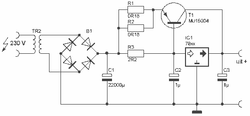
This is a heavy diet, which can deliver 10A stabilized. The circuit is built around a normal 78xx controller, but for extra power equipped with T1. For the 78xx can be taken any type. Keep in mind that the...
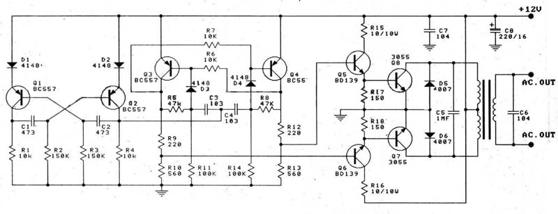
A 12V car battery is recommended as the input for this circuit, utilizing the 2N3055 transistor as the amplifier. This configuration can deliver a power output of up to 100W, making it suitable for use in battery chargers, emergency...
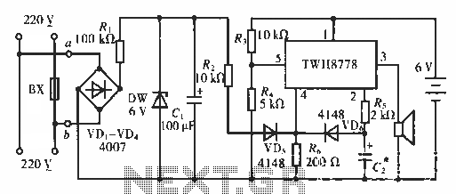
The circuit functions as an AC blown fuse alarm. When the fuse (BX) is intact, 220 V AC voltage passes through a bridge rectifier composed of diodes VD1 to VD4. Resistor R1 limits the current, and the output is...
This slideshow is based on the LED Design Ideas Collection, which features a compilation of LED-related circuits and design applications submitted by readers and published in EDN's Design Ideas section. Users can browse through the circuit schematics in this...
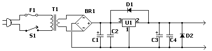
The fixed voltage power supply is useful in applications where an adjustable output is not required. This supply is simple, but very flexible as the voltage it outputs is dependent only on the regulator and transformer you choose. The...
Several individuals have mentioned that the house number is difficult to read at night. The number comprises four digits mounted on a structural column that supports a section of the roof. In response to these concerns, a request has...