
Power Quality Improvement Using Switch Mode Regulator
The phase-controlled AC voltage regulator is designed to manage voltage levels effectively, ensuring that the output voltage remains stable despite fluctuations in the input voltage. The use of back-to-back SCRs allows for bidirectional control of the AC waveform, which is essential for maintaining the desired output voltage. The inclusion of diodes in the circuit aids in protecting the SCRs from reverse voltage conditions, enhancing the overall reliability of the system.
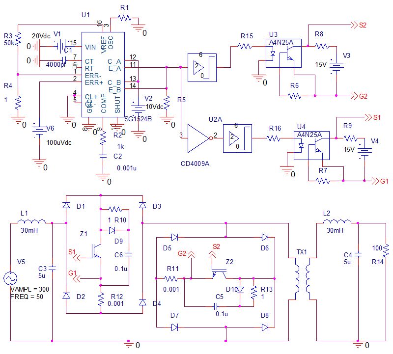
The control circuit plays a pivotal role in the operation of the regulator. By employing a pulse width modulation (PWM) technique, the SG1524B IC chip generates control signals that dictate the timing of the SCRs' conduction. This method allows for precise control over the output voltage, adapting to changes in load conditions and input voltage variations. The high-frequency operation of the SMPS minimizes energy losses and improves efficiency, making it suitable for a wide range of applications.
In terms of performance, the regulator is expected to mitigate common power quality issues, particularly voltage sags, by rapidly adjusting the output voltage in response to disturbances. The design also considers factors such as thermal management and component ratings to ensure that the system can operate reliably under varying load conditions. Overall, the switch-mode AC voltage regulator presents a modern solution to voltage regulation challenges in industrial and commercial settings, combining advanced semiconductor technology with efficient control strategies.Phase controlled AC voltage regulator, (a) Using back to back SCR and diode and (b) using inverse parallel SCR (c) Using diode-bridge and single SCR Figure 30. Input and output voltage waveforms for input 250V and output 300V. V1(V5): Input voltage- bottom figure, V(R14:2): Output voltage top figure. Power quality describes the quality of voltage and current. It is an important consideration in industries and commercial applications. Power quality problems commonly faced are transients, sags, swells, surges, outages, harmonics and impulses [ 1 ]. Among these voltage sags and extended under voltages have large negative impact on industrial productivity, and could be the most important type of power quality variation for many industrial and commercial customers [ 1 - 5 ].
Voltage sags is mainly due to the fault occurring in the transmission and distribution system, loads like welding and operation of building construction equipment, switching of the loaded feeders or equipments. Both momentary and continuous voltage sags are undesirable in complex process controls and household appliances as they use precision electronic and computerized control.
Major problems associated with the unregulated long term voltage sags include equipment failure, overheating and complete shutdown. Tap changing transformers with silicon-controlled rectifiers (SCR) are usually used as a solution of continuous voltage sags [ 6 ].
They require large transformer with many SCRs to control the voltage at the load which lacks the facility of adjusting to momentary changes. Some solutions have been suggested in the past to encounter the problems of voltage sag [ 7 - 11 ]. But these proposals have not been realized practically to replace conventional tap changing transformers.
Now a day`s various power semiconductor devices are used to raise power quality levels to meet the requirements [ 12 ]. Several AC voltage regulators have been studied as a solution of voltage sags [ 13 - 18 ]. In [ 13 ] the input current was not sinusoidal, in [ 14 - 16 ] the efficiency of the regulator was not analyzed and in [ 17 - 18 ] the input power factor was very low and the efficiency is also found poor.
Compact and fully electronic voltage regulators are still unavailable practically. Dynamic Voltage Restorer (DVR) is sometimes used to regulate the load side voltage [ 19 - 21 ]. The DVR requires energy storage device to compensate the voltage sags. Flywheels, batteries, superconducting magnetic energy storage (SMES) and super capacitors are generally used as energy storage devices. The rated power operation of DVR depends on the size and capacity of energy storage device which limits its use in high power applications.
Whereas, switching regulator needs no energy storage devices, therefore, can be used both in low power and high power applications. The objective of this chapter is to describe the operation and design procedure of a switch mode AC voltage regulator.
Firstly, some reviews of the regulators are presented then the procedure of design and analysis of a switch mode regulator is described step by step. Simulation software OrCAD version 9. 1 [ 22 ] is used to analyze the regulator. The proposed regulator consists mainly two parts, power circuit and control circuit. The power circuit consist two bi-directional switches which serve as the freewheeling path for each other.
A signal generating control circuit is to be associated with the power circuit for getting pulses of the switches. In the control circuit, a commercially available pulse width modulator IC chip SG1524B is used, thus circuit is compact and more viable.
A switching-mode power supply (SMPS) is switched at very high frequency. Conversion of both step down and ste 🔗 External reference
Related Circuits
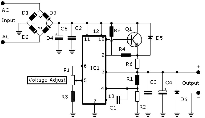
DC power supply 3-30V 3-30V 3A stabilized power supply. Go to that page to read the explanation about the above power supply related circuit diagram. The DC power supply described is a versatile device capable of providing a stable output...
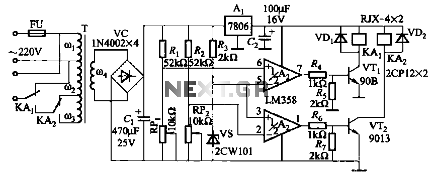
It utilizes two LM358 operational amplifiers, A2 and Ar, to create a voltage measurement comparison control circuit for upper and lower limit voltage settings. The circuit includes a Raspberry Pi adjustment potentiometer (RPi) and an additional potentiometer (RP2) to...
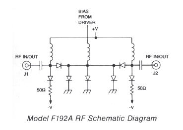
High-speed frequency range of 0.2 to 18 GHz with 80 dB isolation. Features non-reflective performance, low Voltage Standing Wave Ratio (VSWR), and minimal insertion loss. Compact and lightweight design. This electronic component is designed to operate efficiently across a broad...
This circuit detects the AC audio voltage supplied to car radio loudspeakers and visually represents it as power using an LED bar graph, creating an appealing visual effect. It is designed to accommodate typical car radio output power ranges...
One of the simplest methods of metal detecting is through a beat frequency oscillator. The circuit consists of two balanced oscillators: one provides a reference signal, while the other acts as the detector element. The frequency of the reference...
The TS2418 is a monolithic integrated circuit telephone tone ringer that utilizes a bridge diode. When paired with an appropriate transducer, it serves as a replacement for traditional electromechanical bells. This device is compatible with either a piezo transducer...