
Relay control auto-transformer AC power supply circuit
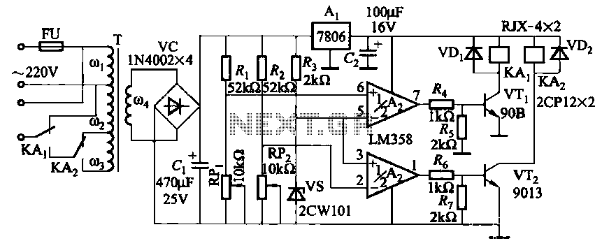
The circuit employs the LM358, a dual operational amplifier, to compare two voltage levels. The first op-amp (A2) is configured to monitor the upper limit voltage, while the second op-amp (Ar) monitors the lower limit voltage. The output of these op-amps will indicate whether the measured voltage exceeds the upper limit or falls below the lower limit.
The potentiometer labeled RPi is connected to the non-inverting input of A2, allowing users to adjust the reference voltage to set the desired upper limit. Similarly, the potentiometer RP2 is connected to the non-inverting input of Ar for adjusting the lower limit voltage. The inverting inputs of both op-amps are connected to the voltage being measured, which is compared against the set reference voltages.
When the measured voltage exceeds the upper limit, the output of A2 will switch to a high state, indicating an over-voltage condition. Conversely, if the measured voltage drops below the lower limit, the output of Ar will switch to a high state, signaling an under-voltage condition. This dual comparison setup enables effective monitoring of voltage levels and can be used in various applications, including power supply regulation, battery management systems, and safety alarms.
The circuit can be further enhanced by integrating additional components such as LEDs or relays that can be activated based on the op-amp outputs, providing visual or physical indications of voltage status. This design ensures that the system can react promptly to voltage deviations, maintaining operational safety and reliability.It uses two LM358 op amp A2 and Ar as an upper limit and a lower limit voltage electrical voltage measurement comparison control circuit. RPi adjustment potentiometer and RP2, can change the upper limit voltage and lower voltage setting.
Related Circuits
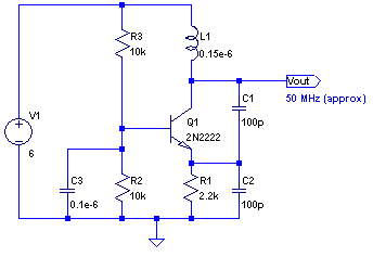
The core of any transmitter is typically an oscillator circuit, and in simple transmitters, such as QRSS devices, a crystal is often used. Frequency adjustment is achieved by modifying the capacitance to ground on one of the crystal's legs....
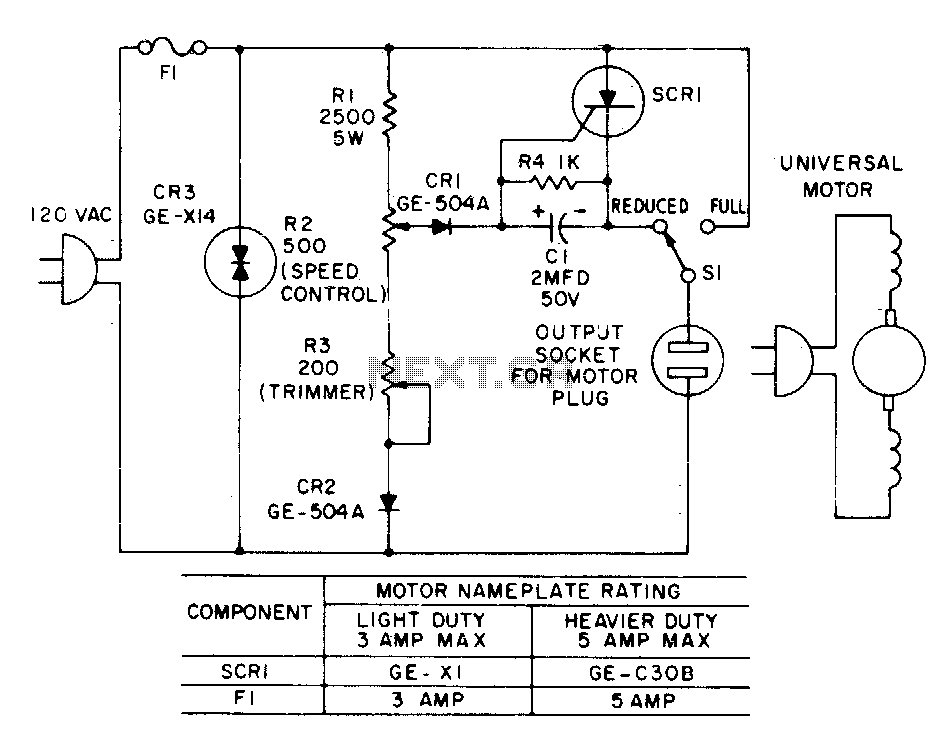
Most standard household appliances and portable hand tools can be adapted for variable-speed operation using a simple half-wave SCR phase control. This device can serve as the speed control unit for typical loads, provided they utilize series universal (brush...
One of the most notable RF amplifiers documented is Wes Hayward's post-mixer amplifier in the Progressive Communications Receiver. It is recognized as a highly effective high-level RF amplifier, operating with a standing current of 50 mA, which allows it...
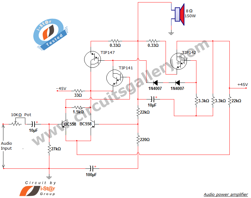
This document presents a new audio power amplifier schematic utilizing TIP darlington pair transistors. It is suitable for both home audio and car audio amplifiers. The TIP142 and TIP147 darlington pair transistors create a push-pull high-power amplifier configuration, while...
This circuit is used to power an LED with a voltage of 230V. The 230V must be reduced to meet the LED's voltage requirements. To achieve this, a circuit is necessary as described below. The circuit designed to power an...
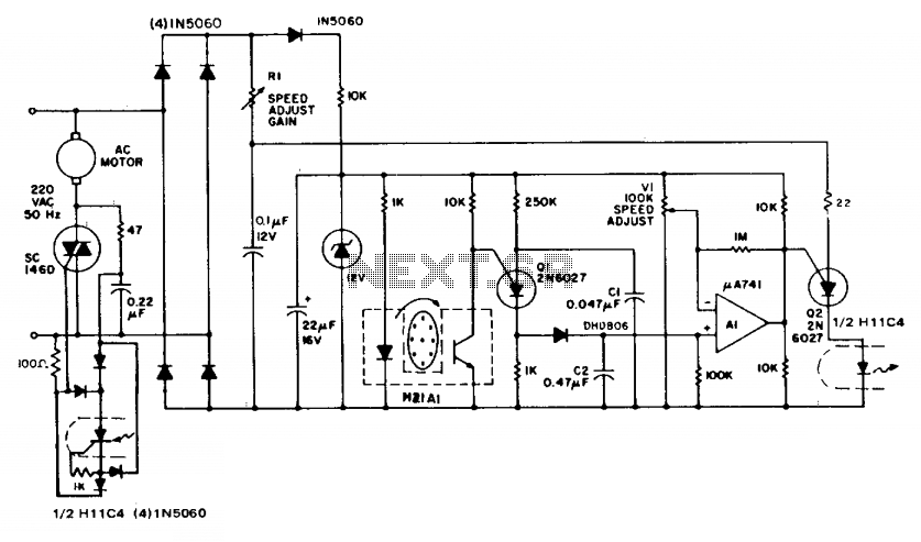
The circuit demonstrates feedback speed regulation for a standard AC induction motor, a task that is typically challenging to achieve without the use of an expensive generator-type precision tachometer. When the apertured disc connected to the motor shaft allows...