
Power supplies for microcontroller based projects

The design of a power supply for microcontroller-based projects should prioritize reliability and safety. A typical configuration would include a 7805 voltage regulator, which ensures a stable 5V output, suitable for most microcontrollers. The input voltage should be selected based on the regulator's specifications, with a common choice being a 12V supply capable of delivering at least 500mA. This allows for some overhead in current capacity, accommodating transient loads from the microcontroller and other components.
To enhance circuit protection, a series diode is recommended to prevent damage from reverse polarity connections. The input capacitor (100uF/25V) should be placed as close to the regulator as possible to filter out any noise and stabilize the input voltage. On the output side, a 10uF capacitor serves to smooth the output voltage and reduce ripple. The thermal management of the regulator is critical; if it becomes excessively hot, a heat sink must be added to dissipate heat effectively, ensuring the regulator operates within its safe temperature range.
Decoupling capacitors (typically 100nF) should be placed near the microcontroller and other integrated circuits to filter out high-frequency noise, which can interfere with the operation of sensitive components. For larger circuits, additional bulk decoupling capacitors (10uF) should be distributed across the PCB to maintain power integrity.
Incorporating an LED indicator connected through a resistor to the output provides a visual cue that the power supply is operational, contributing to safer experimentation and development practices. The design should also include a fuse for battery-powered applications, enhancing safety by preventing excessive current flow that could lead to component damage.
Overall, careful attention to component selection, layout, and thermal management will yield a robust power supply suitable for various microcontroller applications.Here we are working on small microcontrollers like PICs and Atmel series, which are operating from 5V and require less than 100mA for complete system typically. There are some PICs operate from lower voltages like 3. 3V, but the principals for power supply are almost the same. This article covers power supplies with low power output which is suitable as simple source of reliable low voltage power for the microcontroller based projects.
If you need currents higher than 1A to operate your circuit, you need high power capable power supply. When developing circuits unexpected accidents are not uncommon. For an example short circuit due to Solder Bridge or a wire placed in wrong hole are mostly seen. If your power supply is not current limited and has rated few Amps, then these accidents can course severe damages to you and your valuable project.
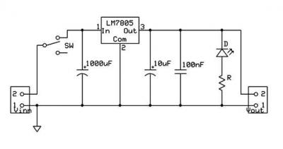
So always using current limited power supply is good idea. It is recommended to use power supply based on 7800 series regulator for small microcontroller based project. 7805 regulator is widely used cheap and reliable solution which will out put regulated +5V on its O/P terminal.
A good power source would be 12V 500mA power pack which is powered by mains power outlet. The regulator should not be too much larger than actual expected current demand of project. When estimating power, calculate as 5mA for MCU chip, about 3 mA for TTL/CMOS ICs, 10mA for regular size LED etc. Always refer datasheets of your parts to find out their operating standard and peak currents and make power supply rated to peak operating current of project.
For a load of 50mA or less use a 78L05 which is rated at 100mA but will deliver a bit more. If you need more than 50mA for your circuit, 7805 regulator can supply about 1A with heat sink on it. Having series diode in the +ve line before the input capacitor is good idea because this protects power supply when the power-pack is connected the wrong way (it happens quite often during experiments).
The input capacitor should be close to the regulator IC and at least 100uF/25V. On the output side of the regulator you should have a minimum 10uF capacitor. If the regulator gets too hot to hold comfortably for a few seconds securely between two fingers you need a larger regulator or add a heat sink. Remember, the capacitors must be close to the regulator so don`t run long wires from the board to the regulator to get to the heat sink.
It is good practice to have decoupling capacitor near MCU and other major ICs. This decoupling capacitor should be 100nF in general. If your circuit is large complex one or has components spared all over the PCB, (or Veroboard or breadboard) include few 10uF capacitors among other components which are tied to +ve and ground lines. This improves power quality and stability all over the board. Also it is good idea to connect LED through 330 ohm resistor, directly to your power supply out put. When you have connected power-pack LED will lit and indicate you power is ON and will help you to avoid unfortunate accidents.
Refer following circuit schematic to design your power supply. Also if you think it is worth, design small PCB for your power supply board and populate components on it. Never use a battery power supply without a fuse; especially a lead-acid battery. Locate the fuse close to the battery terminal so that it protects the leads as well. Many batteries can deliver large short circuit currents; well enough to fry lot of valuable circuitry and leave burn marks on you.
Any way having fuse will not protect your circuit. But will prevent thing going worse. Do not use a PC AT or ATX power supply t 🔗 External reference
Related Circuits
The FM Wireless Microphone has gained popularity among both beginners and experienced constructors. It has been utilized in guitars and as a component of remote control systems. There have been numerous requests for a higher-powered circuit with improved microphone...
The losses in a bridge rectifier can become significant when low voltages are being rectified. The voltage drop across the bridge is approximately 1.5 V, which represents about 25% of an input voltage of 6V. The loss can be...
A micro power supply unit (PSU) is designed to power a breadboard with a voltage output of 5 volts. It can be connected to a 9V battery, a 12V source, or any other direct current (DC) power supply ranging...
The power supply, with electronic stabilization - mainly those of laboratories - should be protected from overcurrent that emanates from short-circuits, erroneous association, or damage of repaired appliances. The circuit offers effective protection in power supply with output voltage...
The starting ability of intermediate frequency power is a crucial performance index that significantly impacts the quality and usability of the apparatus. This has been a focal point and a challenge in the industry, leading to various methods aimed...
The rectifier bridge voltage is determined by the U2 element; refer to its datasheet for the maximum voltage specifications. The minimum voltage at this pin should not fall below approximately 9V, or 6.5V if low-dropout type U2 and U3...